Peak value sampling retaining circuit and method thereof used for switch power supply

A technology of peak hold circuit and peak sampling, which is applied in the direction of logic circuit coupling/interface, logic circuit connection/interface layout, etc. using field effect transistors, which can solve the problem that the speed of the sample hold circuit decreases and the output voltage cannot reproduce the input signal very well Voltage and other issues to achieve the effect of enhancing load driving capability and avoiding charge accumulation

Inactive Publication Date: 2012-03-28
ZHEJIANG VOCATIONAL COLLEGE OF COMMERCE
View PDF3 Cites 13 Cited by
  • Summary
  • Abstract
  • Description
  • Claims
  • Application Information

AI Technical Summary

Problems solved by technology

[0005] The disadvantage of the existing sample-and-hold circuit is that when the hold switch 106 is turned on and the sample switch 102 is not turned on, the charge on the sampling capacitor will flow to the hold capacitor 108 to charge the hold capacitor until the charge on the sample capacitor 105 is The charging of the holding capacitor is completed only when the voltage is equal to the voltage on the holding capacitor 108, so that the final result is that the voltage on the holding capacitor 108 is the voltage when the sampling capacitor 105 and the holding capacitor 108 are balanced, rather than the voltage of the input line 101, The output voltage does not reproduce the voltage of the input signal very well
Since the existing technology does not have this link for compensating the charging current, the speed of the entire sample-and-hold circuit will decrease

Method used


Image

  • Peak value sampling retaining circuit and method thereof used for switch power supply
  • Peak value sampling retaining circuit and method thereof used for switch power supply
  • Peak value sampling retaining circuit and method thereof used for switch power supply

Examples


Embodiment Construction

[0055] The content of the present invention will be further described below in conjunction with the accompanying drawings.

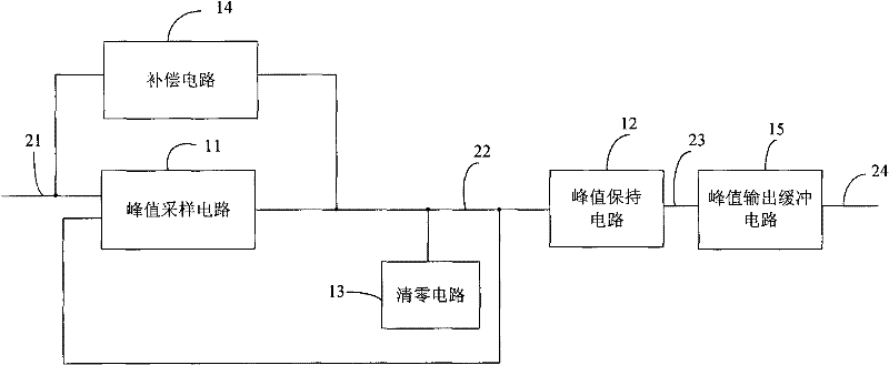
[0056] peak sample-and-hold circuits, such as image 3 , Figure 4 As shown, it includes a peak sampling circuit 11, a compensation circuit 14, a peak hold circuit 12, a peak output buffer circuit 15 and a clearing circuit 13:

[0057] The peak sampling circuit 11 samples the peak voltage 22 of each time point of the input signal 21;

[0058] The compensation circuit 14 is to compensate the charging current of the sampling capacitor 37 of the peak sampling circuit 11, so that the speed of the peak sampling circuit will be accelerated;

[0059] The peak hold circuit 12 holds the peak voltage 22;

[0060] The peak output buffer circuit 15 enhances the output load driving capability of the peak hold circuit 12;

[0061] The clearing circuit 13 clears the peak voltage of the previous period output by the peak sampling circuit 11 to zero in time after the...


PUM


Abstract

The invention discloses a peak value sampling retaining circuit and a method thereof used for a switch power supply, wherein the peak value sampling retaining circuit comprises a peak value sampling circuit, a compensating circuit, a peak value retaining circuit, a peak value output buffering circuit and a clear circuit, the peak value sampling circuit is used for sampling peak value voltage at each time point of input signals, the compensating circuit is used for carrying out charging current compensation on sampling capacitance of the peak value sampling circuit, so as to enable the speed of the peak value sampling circuit to be quickened, the peak value retaining circuit is used for retaining voltage output by the peak value sampling circuit, the peak value output buffering circuit is used for enhancing load outputting capacity of the peak value retaining circuit, the clear circuit is used for timely clearing peak value voltage of a previous period, which is output by the peak value sampling circuit, so as to be convenient to carry out peak value sampling in a next period. In the invention, the peak value of input signals can better and faster reappear, and the peak value sampling retaining circuit can be applied on a switch power supply system.

Description

technical field [0001] The invention relates to a peak sampling and holding technology, in particular to a peak sampling and holding circuit used in a switching power supply and a method thereof. Background technique [0002] In a power supply system, the magnitude of the input voltage is an important factor that determines whether the system can work normally, so it is necessary to sample the line voltage through sample and hold. figure 1 It is the circuit diagram of the existing sample and hold circuit. The sample and hold circuit includes: a sampling circuit 110 and a hold circuit 111 . Described sampling circuit 110 comprises the control line 104 of sampling switch 102, sampling capacitor 105 and sampling switch, one end of sampling switch 102 is connected with input line 101, the other end of sampling switch 102 is connected with one end of sampling capacitor 105, the other end of sampling capacitor 105 grounding; when the control line 104 is at a high level, the samp...

Claims


Application Information

Patent Timeline
Patent Type & Authority Applications(China)
IPC IPC(8): H03K19/0185
Inventor 王文建
Owner ZHEJIANG VOCATIONAL COLLEGE OF COMMERCE
Why Eureka
Try Eureka