Method and system for reducing trace length and capacitance in a large memory footprint background

A storage module and storage channel technology, applied to static memory, backplanes for installing orthogonal PCBs, instruments, etc., can solve problems such as low speed

Inactive Publication Date: 2012-03-28
HEWLETT-PACKARD ENTERPRISE DEV LP
View PDF5 Cites 7 Cited by
  • Summary
  • Abstract
  • Description
  • Claims
  • Application Information

AI Technical Summary

Problems solved by technology

Therefore, a heavily loaded bus fitted with the maximum number of DIMM connectors will result in lower speeds due to capacitive effects of long traces affecting timing parameters

Method used


Image

  • Method and system for reducing trace length and capacitance in a large memory footprint background
  • Method and system for reducing trace length and capacitance in a large memory footprint background
  • Method and system for reducing trace length and capacitance in a large memory footprint background

Examples


Embodiment Construction

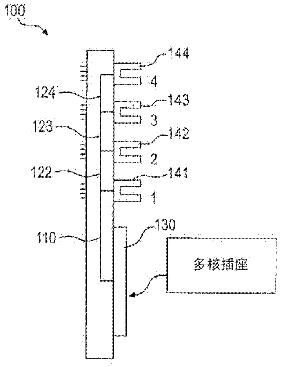
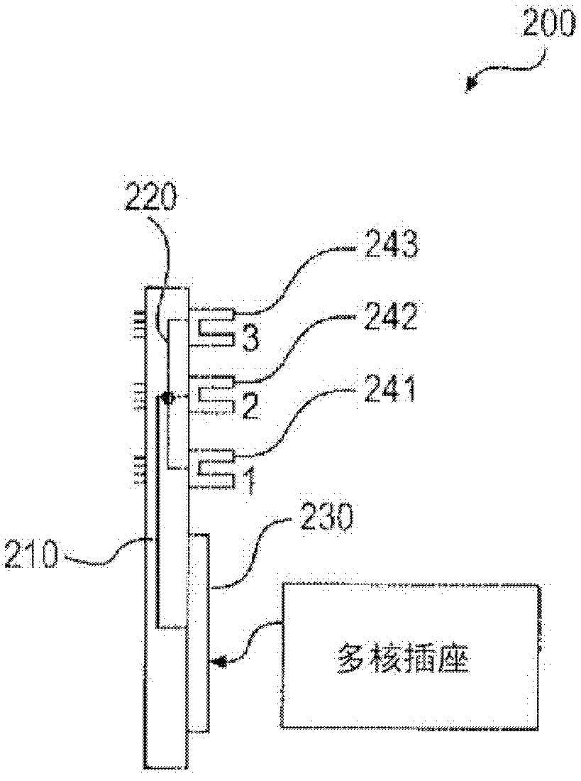
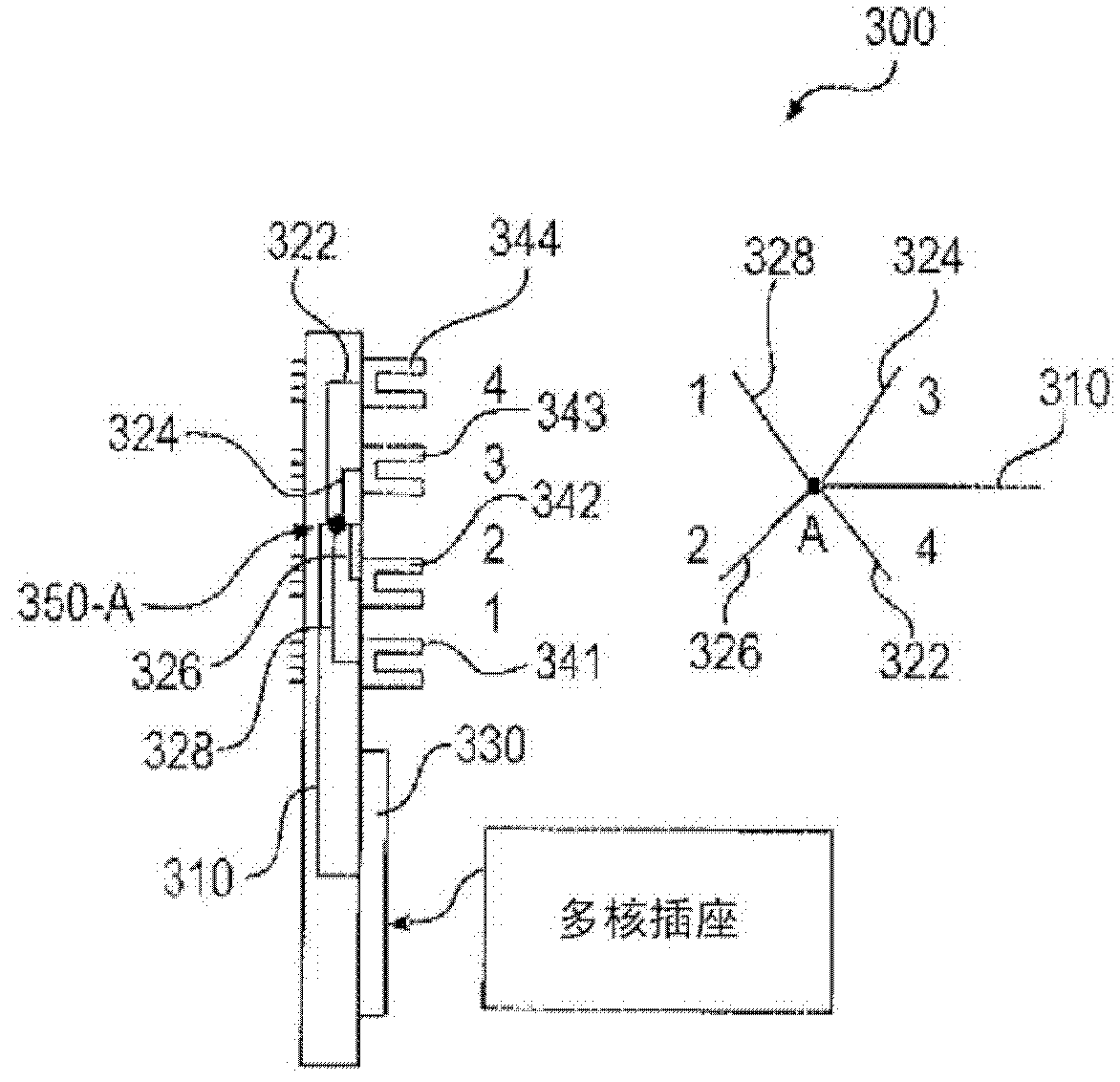
[0011] Systems and methods for reducing trace length and capacitance in large memory footprints are described. As noted above, it is desirable to maximize the number of dual in-line memory module (DIMM) connectors per memory channel while operating at the highest possible frequency that the memory channel can support. As more DIMM connectors are used per memory channel, the total bus bandwidth is affected by trace length and trace capacitance. To reduce overall trace length and trace capacitance, the system and method use a palm tree topology, ie, a back-to-back DIMM layout, to mirror surface mount technology (SMT) DIMM connectors (rather than through-hole connectors) Arranged back-to-back on each side of the printed circuit board (PCB). The system and method can improve signal propagation time compared to conventional topologies such as daisy-chain, T-shaped and star topologies that place all DIMM connectors (or through-hole DIMM sockets) on one side of the PCB.

[0012] f...


PUM


Abstract

A method and system are disclosed to reduce trace length and capacitance in a large memory footprint. When more dual in-line memory module (DIMM) connectors are used per memory channel, the overall bus bandwidth may be affected by trace length and trace capacitance. In order to reduce the overall trace length and trace capacitance, the system and method use a palm tree topology placement, i.e., back-to-back DIMM placement, to place surface mount technology (SMT) DIMM connectors (instead of through-hole connectors) back-to-back in a mirror fashion on each side of a printed circuit board (PCB). The system and method may improve signal propagation time when compared to the commonly used traditional topology placements in which all DIMM connectors are placed on one side of the PCB.

Description

Background technique [0001] Current printed circuit board (PCB) technology can arrange dual in-line memory module (DIMM) connectors using several different types of topologies. It is desirable to maximize the number of DIMM connectors per memory channel to achieve high memory capacity while operating at the highest possible frequency that the memory channel can support. One solution is to route all DIMM connectors close to the multicore sockets to keep trace lengths as short as possible. However, when more and more DIMM connectors are supported for higher storage capacity, the signal traces connecting the DIMM connectors are lengthened in conventional topologies. For example, in the case of double data rate 2 (DDR2) memory technology, 4 DIMM connectors per memory channel routed in conventional topologies can achieve marginal results at 667MHz. [0002] Also, by using through-hole DIMM connectors and by placing the through-hole DIMM connectors on only one side of the PCB, the...

Claims


Application Information

Patent Timeline
Patent Type & Authority Applications(China)
IPC IPC(8): G11C5/06H01R12/57
CPCH05K2201/044H05K1/14G11C5/066H05K1/114H05K1/0237H05K1/181H05K2201/10545H05K2201/10189H05K2201/09227Y10T29/49147Y02P70/50
Inventor R·M·卡德里S·F·康特里拉斯
Owner HEWLETT-PACKARD ENTERPRISE DEV LP
Why Eureka
Try Eureka