Imaging device

A technology of camera device and camera surface, which can be used in installation, image communication, television, etc., and can solve problems such as light reduction.

Active Publication Date: 2012-03-28
PANASONIC CORP
View PDF6 Cites 4 Cited by
  • Summary
  • Abstract
  • Description
  • Claims
  • Application Information

AI Technical Summary

Problems solved by technology

In order to obtain an image with an extended depth of field, the F value (nanbar) of the imaging optical system is increased, but when the F value is increased, the amount of light decreases

Method used


Image

  • Imaging device
  • Imaging device
  • Imaging device

Examples


Embodiment approach 1

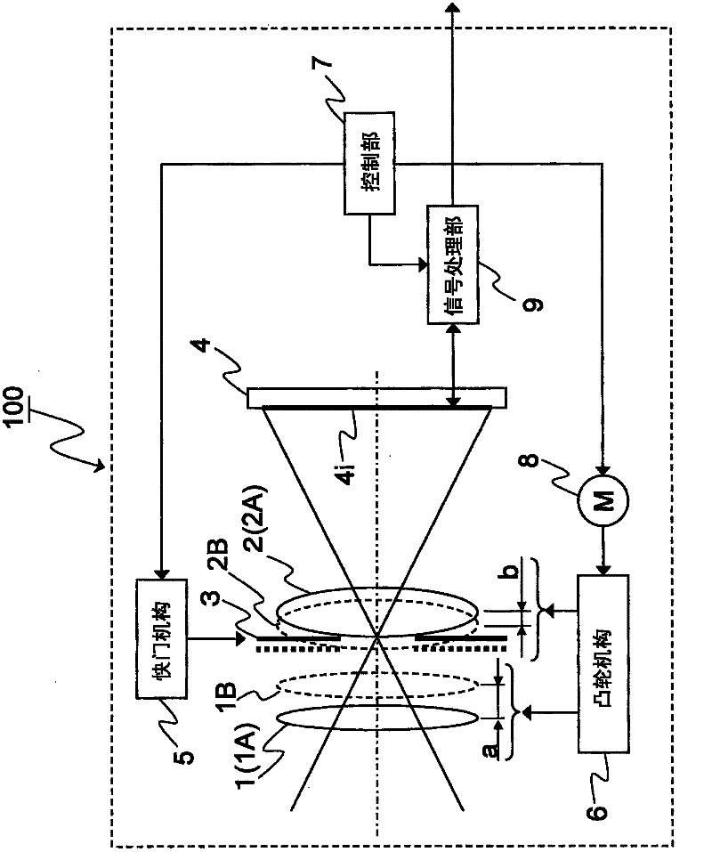
[0045] figure 1 It is a schematic diagram showing the configuration of the imaging device 100 according to Embodiment 1 of the present invention. The imaging device 100 is equipped with: a non-telecentric imaging optical system composed of a first lens 1, a second lens 2, a diaphragm 3, and an imaging element 4 having an imaging surface 4i; a shutter mechanism 5; a cam mechanism including a cam cylinder and a fixed cylinder. 6; a control unit 7; a motor 8; and a signal processing unit 9.

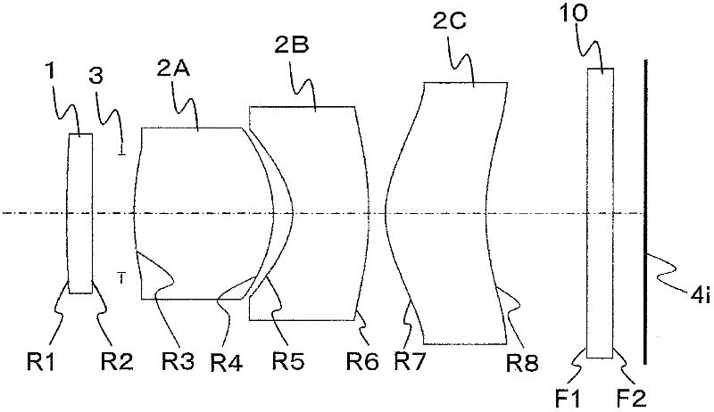
[0046] The first lens 1 is disposed closer to the subject side than the second lens 2 . Light from a subject enters the second lens 2 after passing through the first lens 1 . The second lens 2 is arranged between the first lens 1 and the imaging element 4 . The light passing through the second lens 2 is detected on the imaging surface 4 i of the imaging element 4 .

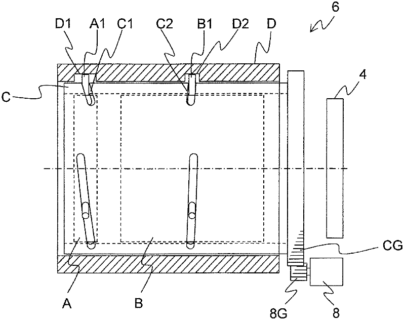
[0047]The cam mechanism 6 and the motor 8 constitute a position changing unit. The motor 8 operates the cam mechanism 6 b...

Embodiment approach 2

[0115] Next, a configuration in which the amount of change in the distance between the first lens 1 and the second lens 2 and the amount of change in the distance between the second lens 2 and the imaging surface of the imaging element 4 are the same will be described.

[0116] Figure 15 It is a schematic diagram showing the configuration of the imaging device 101 of this embodiment. The imaging device 101 includes a non-telecentric imaging optical system including a first lens 1 , a diaphragm 3 , a second lens 2 , and an imaging element 4 ; a shutter mechanism 5 ; a control unit 7 ; a motor 8 ; The second lens 2 and the diaphragm 3 are held by the inner barrel 12 , and the first lens 1 and the imaging element 4 are held by the outer barrel 13 .

[0117] The inner barrel 12 and the motor 8 constitute a position changing unit. The motor 8 moves the inner barrel 12 from an initial position (solid line) 12A to a final position (broken line) 12B based on a control signal from t...


PUM


Abstract

The disclosed imaging device is provided with: a first lens (1); a second lens (2), to which light that has passed through the first lens (1) is incident; an image-side non-telecentric imaging optical system, which contains an imaging element (4) having an imaging surface (4i) that detects light that has passed through the second lens (2); a position-altering unit (a cam mechanism (6) and a motor (8)), which, during exposure, alters each of a first distance between the first lens (1) and the second lens (2), and a second distance between the second lens (2) and the imaging element (4); and a signal-processing unit (9) that generates an image using an electrical signal output from the imaging element (4). The imaging element (4) converts to an electrical signal the light arriving at the imaging surface (4i) during exposure during which the first distance and the second distance are changing.

Description

technical field [0001] The present invention relates to imaging devices such as cameras. Background technique [0002] In the imaging device, when the position of the subject is included in the range of the depth of field, it is possible to capture a focused and vivid image. In order to obtain an image with an extended depth of field, the F value (Number) of the imaging optical system is increased. However, when the F value is increased, the amount of light decreases. [0003] Patent Document 1 discloses a technique in which the depth of field is expanded without increasing the F value by adopting a configuration in which at least one of the subject and the lens barrel moves within the exposure time. The configuration disclosed in Patent Document 1 is an effective method for an object-side telecentric optical system such as a microscope. [0004] prior art literature [0005] patent documents [0006] Patent Document 1: JP-A-60-68312 Contents of the invention [0007]...

Claims


Application Information

Patent Timeline
IPC IPC(8): H04N5/232G02B7/04G02B7/08G02B13/00G02B13/18H04N5/225
CPCG02B27/0075G02B7/08H04N5/2353H04N5/23212G02B13/009H04N5/2254H04N23/73
Inventor 今村典广
Owner PANASONIC CORP
Why Eureka
Try Eureka