Stepless speed-changing device

A continuously variable transmission device and bevel wheel technology, which is applied in the direction of transmission devices, belts/chains/gears, mechanical equipment, etc., can solve the problems of increasing manufacturing costs and energy consumption, high performance and manufacturing process requirements, and large device size and weight and other problems, to achieve the effect of reducing the length and weight of the cone, saving the space for the action to be displayed, and reducing the requirements for the manufacturing process

Inactive Publication Date: 2012-04-04
周承岗
View PDF0 Cites 15 Cited by
  • Summary
  • Abstract
  • Description
  • Claims
  • Application Information

AI Technical Summary

Problems solved by technology

[0002] There are many types of continuously variable transmission mechanisms, and the cone-wheel friction drive is the most commonly used structural form. Among them, the "long cone-shifting belt" continuously variable transmission uses a transmission belt and two cone wheels with parallel axes and opposite cone surfaces to realize infinitely variable transmission. The step-variable transmission has obvious advantages such as simple structure, constant power, symmetrical speed change, etc., but the transmission belt is twisted due to the change of the direction of the cone surface, so only a long cone with a very gentle taper can be used to reduce the degree of tw

Method used


Image

  • Stepless speed-changing device
  • Stepless speed-changing device
  • Stepless speed-changing device

Examples


Embodiment Construction

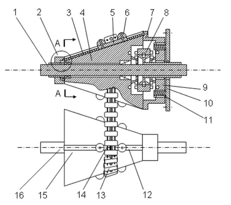
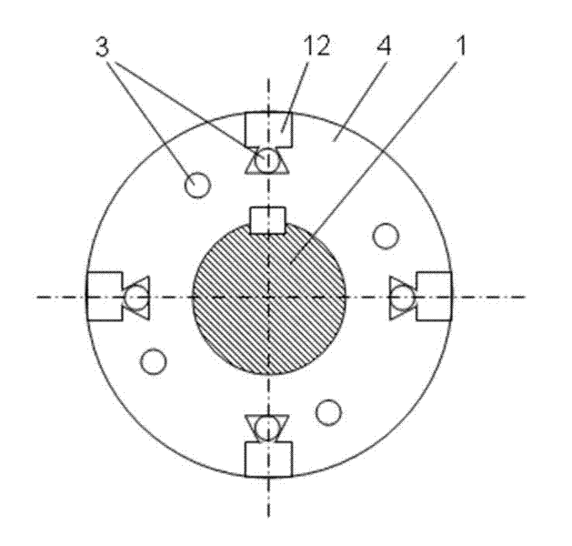
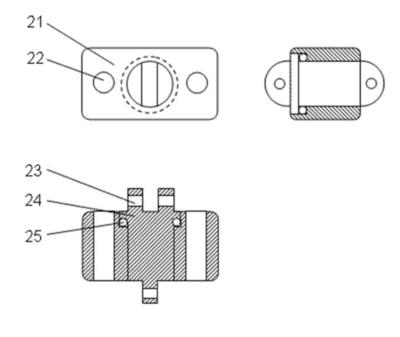
[0021] refer to figure 1 The overall structure shown, figure 2 As shown in the A-A direction view, the input shaft 16 is placed in parallel with the output shaft 1; the input shaft 16 is fixedly connected to the input cone wheel 15, and the output shaft 1 is connected to the output cone wheel 4 in rotation; the input cone wheel 15 and the output cone wheel 4 have conical surfaces In the opposite direction, there are several chutes 12 distributed along the direction of the busbar on the upper side, and each chute has a variable-diameter slider 5 with stoppers 6 at both ends; the transmission chain 13 is placed perpendicular to the input shaft 16, from the variable-diameter slide Pass between the block 6 at block 5 two ends. The drive chain 13 consists of image 3 The unit structure shown is composed of components such as tilting block 21 and roller 25; the chain cores 24 are connected end to end, and are connected by rotating pins at the pin holes 23 at the head and tail to ...


PUM


Abstract

The invention relates to a stepless speed-changing device, comprising an input cone pulley, an output cone pulley and a transmission chain of the input cone pulley and the output cone pulley, wherein the axis of the input cone pulley is parallel to that of the output cone pulley, and the orientation of the cone surface of the input cone pulley is opposite to that of the cone surface of the output cone pulley. The stepless speed-changing device is characterized in that a contact transmission unit on the transmission chain has a rotating freedom degree on the plane which is vertical to the self center point and surrounds the moving direction of the input cone pulley and the outer cone pulley, and can adapt to the change of the orientation of the conical surfaces so as to adjust the inclined direction automatically. The selection of the manufacturing materials of the contact transmission unit and the cone pulleys and the conical-degree sizes of the cone pulleys meet the self-locking condition for generating friction; and the static friction coefficient among the contact transmission unit and the cone pulleys is larger than the tangential value of the conical degree of the cone surface. The peripheries of the input cone pulley and the output cone pulley are provided with sliding grooves along the bus direction, and variable-diameter sliding blocks slide along the sliding grooves to change the working diameter, so that the stepless speed-changing transmission is realized.

Description

technical field [0001] The invention provides a continuously variable transmission related to the fields of automobiles and machinery. Background technique [0002] There are many types of continuously variable transmission mechanisms, and the cone-wheel friction drive is the most commonly used structural form. Among them, the "long cone-shifting belt" continuously variable transmission uses a transmission belt and two cone wheels with parallel axes and opposite cone surfaces to realize infinitely variable transmission. The step-variable transmission has obvious advantages such as simple structure, constant power, symmetrical speed change, etc., but the transmission belt is twisted due to the change of the direction of the cone surface, so only a long cone with a very gentle taper can be used to reduce the degree of twisting, and the size and weight of the device are relatively large. Use occasions are limited. The "cone wheel and steel belt" continuously variable transmiss...

Claims


Application Information

Patent Timeline
IPC IPC(8): F16H9/24
Inventor 周承岗
Owner 周承岗
Why Eureka
Try Eureka