Single-phase transformer

A single-phase transformer and voltage regulating coil technology, applied in the field of transformers, can solve problems such as transportation difficulties, waste of resources, and increase the overall width of the transformer, and achieve the effects of improving operational reliability, facilitating coil winding, and reducing manufacturing risks.

Active Publication Date: 2012-04-04
STATE GRID CORP OF CHINA
View PDF5 Cites 5 Cited by
  • Summary
  • Abstract
  • Description
  • Claims
  • Application Information

AI Technical Summary

Problems solved by technology

[0006] 1) Due to the requirement of impedance voltage, the voltage regulating coil 12 can only be placed within the medium voltage coil 13 and the high voltage coil 14, and the 32 coils of the voltage regulating coil 12 must be drawn out through the end of the high voltage coil 14
Since the terminal voltage of the high-voltage coil 14 is 220KV, it is easy to cause uneven distribution of the field strength at the terminal when the head is passed through, resulting in a very low one-time pass test rate and poor operational reliability.
[0007] 2) Since all the coils are set on the core main column 1, the outer diameter of the high-voltage coil 14 will reach 3 meters, which is very difficult to wind, and the guarantee rate of the radial and axial dimensions of the coil is low
[0008] 3) Since all the coils are mounted on the main column 1 of the iron core, the weight distribution of the transformer is too concentrated, resulting in a complex structure and a lot of materials used for the backing plate used for the transformer, which leads to waste of resources
[0009] 4) Since all the coils are set on the core main column 1, the iron core main column 1 takes up a large space, thereby increasing the overall width of the transformer, making transportation difficult and increasing transportation costs

Method used


Image

  • Single-phase transformer
  • Single-phase transformer
  • Single-phase transformer

Examples


Embodiment Construction

[0023] The present invention will be described more fully hereinafter with reference to the accompanying drawings, in which exemplary embodiments of the invention are illustrated.

[0024] The following is an example of a self-coupling oil-immersed 500KV single-phase transformer. Those skilled in the art can understand that the various embodiments of the present invention are also applicable to other types of single-phase transformers.

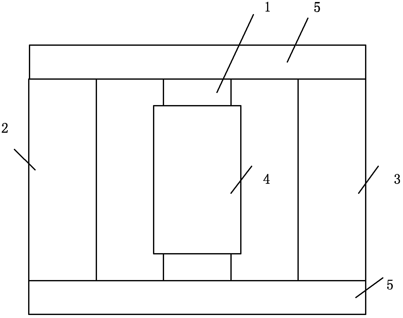
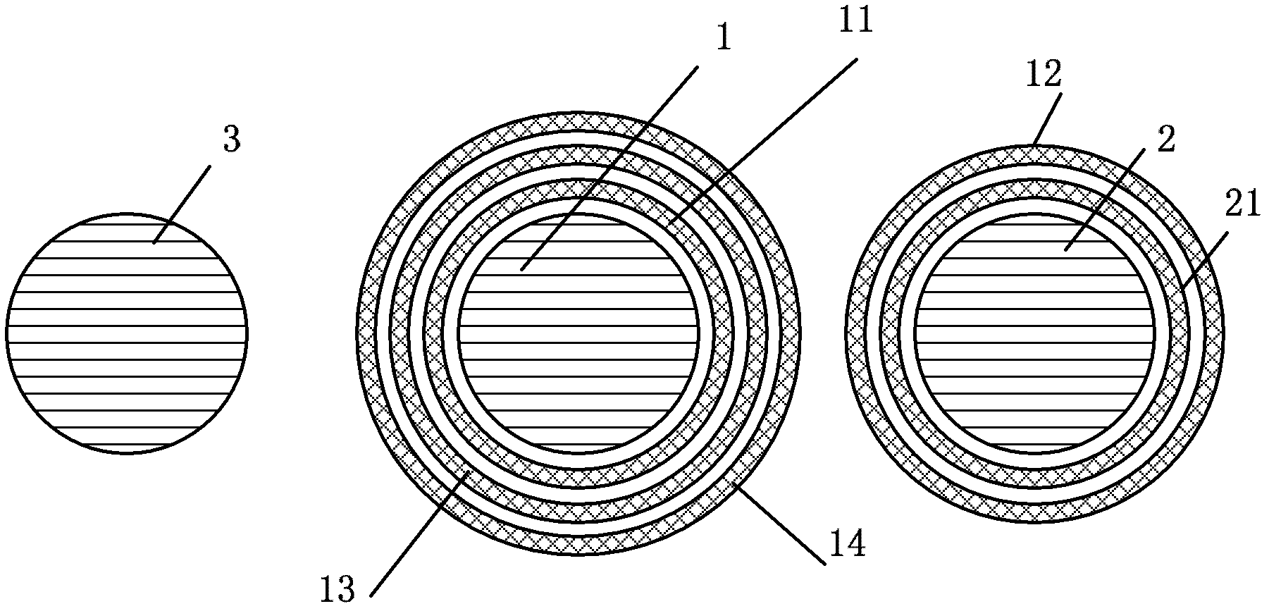
[0025] image 3 It is a top view of an embodiment of the single-phase transformer of the present invention. like image 3 shown, and figure 2 Compared with the prior art shown, the voltage regulating coil 12 is moved from the main column 1 of the iron core to the side column 2 of the iron core, and the excitation coil 21 is placed inside the voltage regulating coil 12 . The excitation coil 21 is connected in parallel with the medium-voltage coil 13 set on the main column 1 of the iron core, so as to achieve the purpose of locking the magn...


PUM


Abstract

The invention discloses a single-phase transformer. The single-phase transformer comprises an iron core main column, a first iron core side column and a second iron core side column, wherein a low-voltage coil, a medium-voltage coil and a high-voltage coil are sleeved on the iron core main column from the inside to the outside in turn; an excitation coil and a voltage regulation coil are sleeved on the first iron core side column from the inside to the outside in turn; and the excitation coil is connected with the medium-voltage coil sleeved on the iron core main column in parallel in order to regulate the voltage of the voltage regulation coil. By sleeving the voltage regulation coil on the first iron core side column, the coil is convenient to wind, manufacturing risks are reduced, the operation reliability of the transformer is improved, and the overall width of the transformer is effectively reduced.

Description

technical field [0001] The invention relates to the field of transformers, in particular to a single-phase transformer. Background technique [0002] A transformer is a static electrical device that uses the principle of electromagnetic induction to convert AC power of one voltage into AC power of another voltage at the same frequency. The basic structure of a transformer is: two or more mutually insulated coils are set on a common iron core, and they are connected to each other through the coupling of the magnetic circuit. Under the action of an applied voltage, an alternating current flows through the primary coil, and an alternating magnetic flux is generated in the iron core. This alternating magnetic flux is simultaneously linked to the primary and secondary coils. According to the law of electromagnetic induction, it can be induced in the secondary coil. EMF. Thus, the secondary coil can supply power to the load, realizing energy conversion. [0003] figure 1 It is...

Claims


Application Information

Patent Timeline
Patent Type & Authority Applications(China)
IPC IPC(8): H01F27/30
CPCH01F30/10H01F27/30
Inventor 刘光辉
Owner STATE GRID CORP OF CHINA
Why Eureka
Try Eureka