Stator or rotor punching mould of power generator

A technology for rotor punching and generator, applied in the field of punching die, can solve problems such as difficulty in ensuring precision requirements, inability to guarantee die quality, increase processing cost, etc., and achieve the effect of saving material cost, reducing deformation and increasing processing cost.

Inactive Publication Date: 2012-04-04
ZHENGZHOU JINYANG ELECTRIC
View PDF5 Cites 2 Cited by
  • Summary
  • Abstract
  • Description
  • Claims
  • Application Information

AI Technical Summary

Problems solved by technology

But no matter what kind of design it is, the blade block is easily deformed, and the quality of the entire mold cannot be guaranteed
At the same time, there are situations where processing is difficult and the cycle is long
In the first fan-shaped circular blade block design with 6 clamping hoops, when the fan-shaped blade blank material is forged, the material needs to be forged into a rectangle, the material utilization rate is low, and the machining allowance is also large (such as image 3 As shown), the material cost is increased; at the same time, when 6 fan-shaped blade blocks are combined into a full-circle blade block, it is necessary to repeatedly sharpen the two spliced ​​surfaces of each blade block according to the angle requirements, so that the 6 The fan-shaped blade blocks are combined into a full-circle blade block, which greatly increases the processing cost; and in the subsequent sharpening of the inner and outer circular blades, due to the thin-walled ring, it is easy to deform during sharpening, and it is difficult to ensure the accuracy requirements
The above-mentioned problems also exist in the design of the full-circle blade block of the second scheme, and the quality of the mold cannot be guaranteed in the end.

Method used


Image

  • Stator or rotor punching mould of power generator
  • Stator or rotor punching mould of power generator
  • Stator or rotor punching mould of power generator

Examples


Embodiment Construction

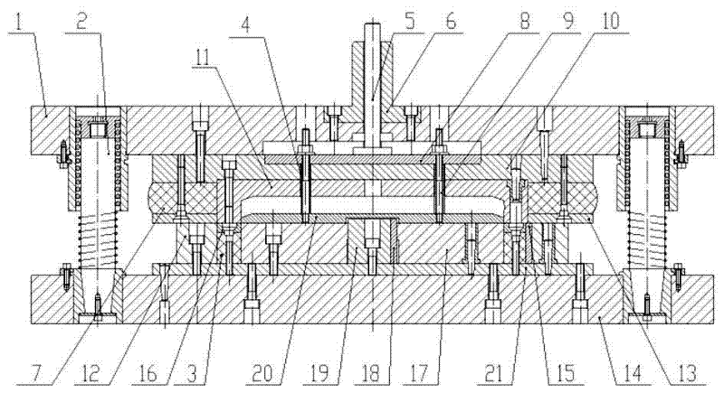
[0016] Such as figure 1 As shown, the generator stator and rotor stamping dies of the present invention include upper and lower mold bases 1, 14, and multiple sets of rolling guides that are evenly distributed and vertically arranged between the upper and lower mold bases 1, 14. Assembly 2, and the upper mold assembly fixed on the lower surface of the upper mold base 1 and the lower mold assembly on the upper surface of the lower mold base 14; the lower mold assembly is respectively fixed on the lower backing plate 21 by the lower backing plate 21 The annular stator die 12, the annular elastic rubber block 3 set in the annular stator die 12, the annular stator stripper plate 16 fixed on the upper ring surface of the annular elastic rubber block 3, and the ring-shaped elastic rubber block 3 located in the The rotor punch 17 is composed of a positioning shaft 19 through a positioning key 18 at the center of the rotor punch 17 for the positioning of the rotor stripping plate 20; ...


PUM


Abstract

The invention discloses a stator or rotor punching mould of a power generator, which comprises upper and lower mould seats, and rolling guide assemblies arranged uniformly and vertically between the upper and lower mould seats, as well as upper and lower mould assemblies fixedly connected to the lower surface of the upper mould seat and the upper surface of the lower mould seat. The stator or rotor punching mould of the power generator disclosed by the invention has the advantages that: the traditional opened annular convex-concave mould is changed into a downwardly opened structure with a sealed top, so that deformation of the convex-concave mould in processing and deformation caused by thermal treatment of parts are reduced so as to reduce the influence of the deformation of the parts on the quality of the mould; a knockout plate, a fixed plate and a convex-concave mould rotor material returning plate are connected together through six groups of uniformly arranged knockout rods to form a rigid material returning device for returning materials, so that the whole circumference in the rotor punching and material returning process is ensured to be stressed evenly; with respect to structures of six assembled fanning strips, the material cost is saved by about 40% in blank material forging process; and the processing expense and processing difficulty of parts are greatly lowered.

Description

technical field [0001] The invention relates to a sheet punching die, in particular to a sheet punching die for a generator stator and rotor. Background technique [0002] When the multi-pole generator stator and rotor stamping dies are used for stator and rotor blanking, since the inner hole of the stator stamping is φ178, the outer diameter is φ225, and the width of one side of the stator stamping is 23.5, therefore, the punch and die Processing requirements are particularly high. At present, there are two relatively mature design schemes. One scheme is that the convex and concave dies adopt the circular blade design of fan-shaped 6-joint tightening hoop (such as figure 1 Shown), another kind of scheme is to make the whole ring blade block design. But no matter which design it is, the blade block is easily deformed, and the quality of the entire mold cannot be guaranteed. At the same time, there are situations where processing is difficult and the cycle is long. In the...

Claims


Application Information

Patent Timeline
Patent Type & Authority Applications(China)
IPC IPC(8): H02K15/02
Inventor 杨春立史清晨刘建风陈书彰魏书玲马清明杨淑霞
Owner ZHENGZHOU JINYANG ELECTRIC
Why Eureka
Try Eureka