Method for machining valve seat of respiratory flow and rhythm control air valve

A breathing flow and air valve control technology, which is applied to the breathing flow rhythm control air valve seat and its processing field, can solve the problems of large valve seat coaxiality error, numerous processing steps, poor precision control, etc., and achieves processing accuracy. Guaranteed, wide processing range, reduced processing program effect

Inactive Publication Date: 2012-04-11
于邦仲
View PDF5 Cites 7 Cited by
  • Summary
  • Abstract
  • Description
  • Claims
  • Application Information

AI Technical Summary

Problems solved by technology

For the valve seat with complex inner cavity structure, when the existing valve seat processing technology is used, the existing processing technology has many processing steps, the accuracy is not easy to control, the surface quality is poor, and the burrs are difficult to remove. The coaxiality error of the valve seat is relatively large

Method used


Image

  • Method for machining valve seat of respiratory flow and rhythm control air valve
  • Method for machining valve seat of respiratory flow and rhythm control air valve
  • Method for machining valve seat of respiratory flow and rhythm control air valve

Examples


Embodiment Construction

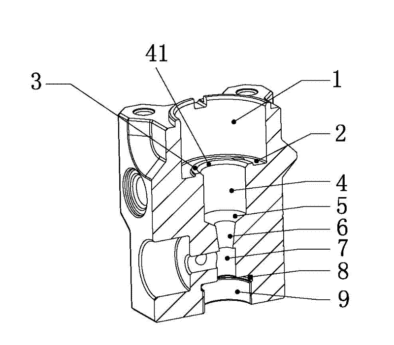
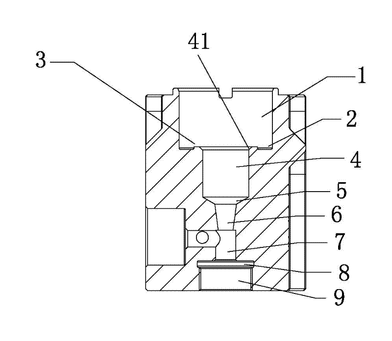
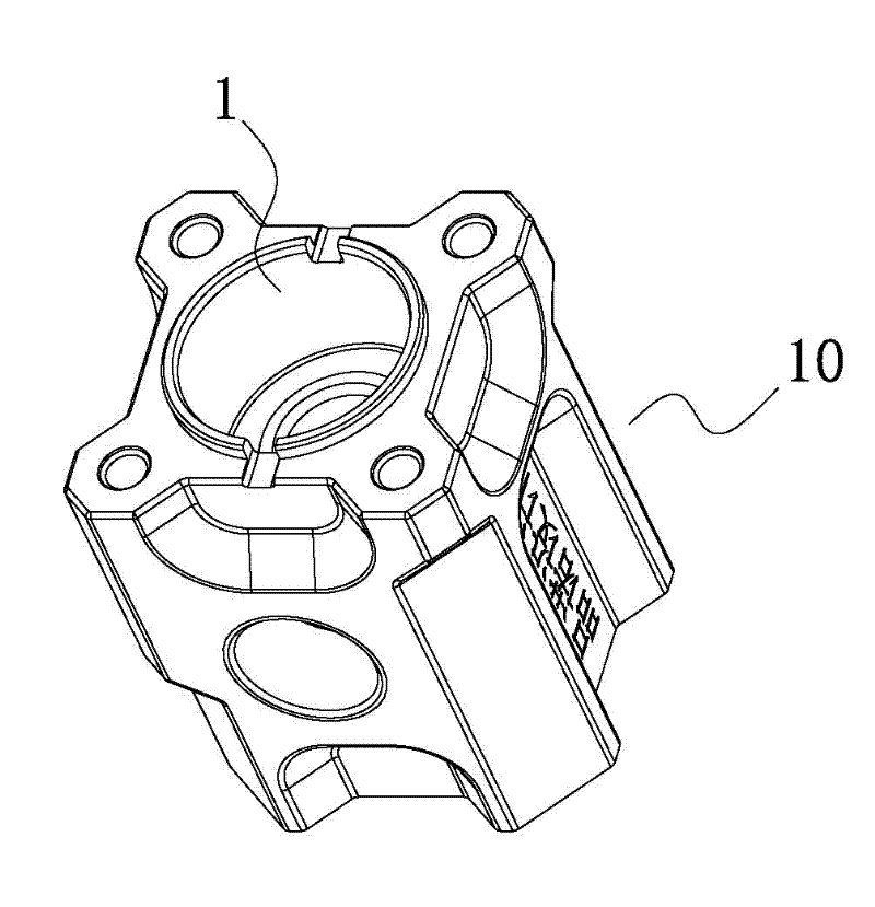
[0024] Such as Figure 1-4 As shown, a valve seat processing method of a breathing flow rhythm control air valve of the present invention is characterized in that: the inner cavity of the valve seat is composed of an upper inner cylindrical surface 1, an inner end surface 2, a stepped surface 3, a middle inner cylindrical surface 4, The upper conical surface 5, the lower conical surface 6, the lower inner cylindrical surface 7, the inner retracting ring groove 8, and the threaded surface 9 are sequentially connected, and the upper inner cylindrical surface 1, the inner end surface 2, the stepped surface 3, and the middle inner cylindrical surface 4. The axis lines of the upper conical surface 5 and the lower conical surface 6 are all on the same central axis; the inner cavity of the valve seat is processed on a CNC lathe, including the following steps in turn:

[0025] 1) Process the metal raw material and turn it into a cylindrical valve seat blank, remove the cylindrical val...


PUM


Abstract

The invention relates to a method for machining a valve seat of a respiratory flow and rhythm control air valve. An inner cavity of the valve seat is formed by sequentially connecting an upper inner cylindrical surface, an inner end surface, a stepped surface, a middle inner cylindrical surface, an upper conical surface, a lower conical surface, a lower inner cylindrical surface, an inner tool retracting ring slot and a threaded surface. The method for machining the valve seat of the respiratory flow and rhythm control air valve comprises the following steps of: uniformly cutting an inner surface by a cyclic program command function of a numerical control machine tool; programming the stepped surface in a vehicle and the inner tool retracting ring slot by a forming cutter; machining an outer surface of the valve seat by automatic programming software of a numerical control machining center; machining thread on the valve seat by a special thread machining device; and finishing the machining of the valve seat by a valve seat material post-machining process. The invention has the advantages of reasonable design and rigorous conception; and due to manufacturing by a new technique, the manufacturing time is saved, the quality performance of products is improved, the stability, the reliability and the safety of operation are reinforced, and the delivery period of the products is shortened.

Description

technical field [0001] The invention relates to the technical field of an air valve device in a medical ventilator, in particular to a breath flow rhythm control air valve seat and a processing method thereof. Background technique [0002] At present, in the processing and manufacturing technology of ordinary valve seats, due to the relatively simple structure of the inner cavity of the valve seat, ordinary clamps are usually used to clamp the valve seat during processing, and simple turning processing with ordinary tools can meet the requirements for use; however, for medical ventilators The inner cavity in the valve seat used in the valve needs to be used for the valve core to move up and down to open and close the gas. Therefore, the coaxiality and smoothness of each surface that the inner cavity in the valve seat and the valve core cooperate with are very high. For such a valve seat with a complex inner cavity structure, when the existing valve seat processing technology...

Claims


Application Information

Patent Timeline
IPC IPC(8): B23P13/02
Inventor 顾志超成其新于邦仲
Owner 于邦仲
Why Eureka
Try Eureka