
High-intensity small pump uncoupling device

A disconnector and high-strength technology, which is applied in the direction of drilling equipment, earthwork drilling, drill pipe, etc., can solve the problems of unsuitable small pumps, etc., and achieve the effects of increasing oil pumping capacity, prolonging service life and reliable performance

Inactive Publication Date: 2012-04-11
梁伟成
View PDF6 Cites 0 Cited by
  • Summary
  • Abstract
  • Description
  • Claims
  • Application Information

AI Technical Summary

Problems solved by technology

[0002] At present, the production process of multi-stage oil pumps is used in oil production plants in oil fields to improve oil recovery efficiency. However, due to the small amount of oil in the formation of some oil wells, multi-stage small pumps are required to operate. Since the multi-stage small pumps cannot be connected on the ground The docking process needs to be completed downhole. The existing problem is that the original connecting tool for connecting the sucker rod and the pump piston is not suitable for small pumps. Therefore, it is necessary to provide a high-strength small pump disconnector to complete the connection between the sucker rod and the pump piston.

Method used


Image

  • High-intensity small pump uncoupling device
  • High-intensity small pump uncoupling device
  • High-intensity small pump uncoupling device

Examples


Embodiment Construction

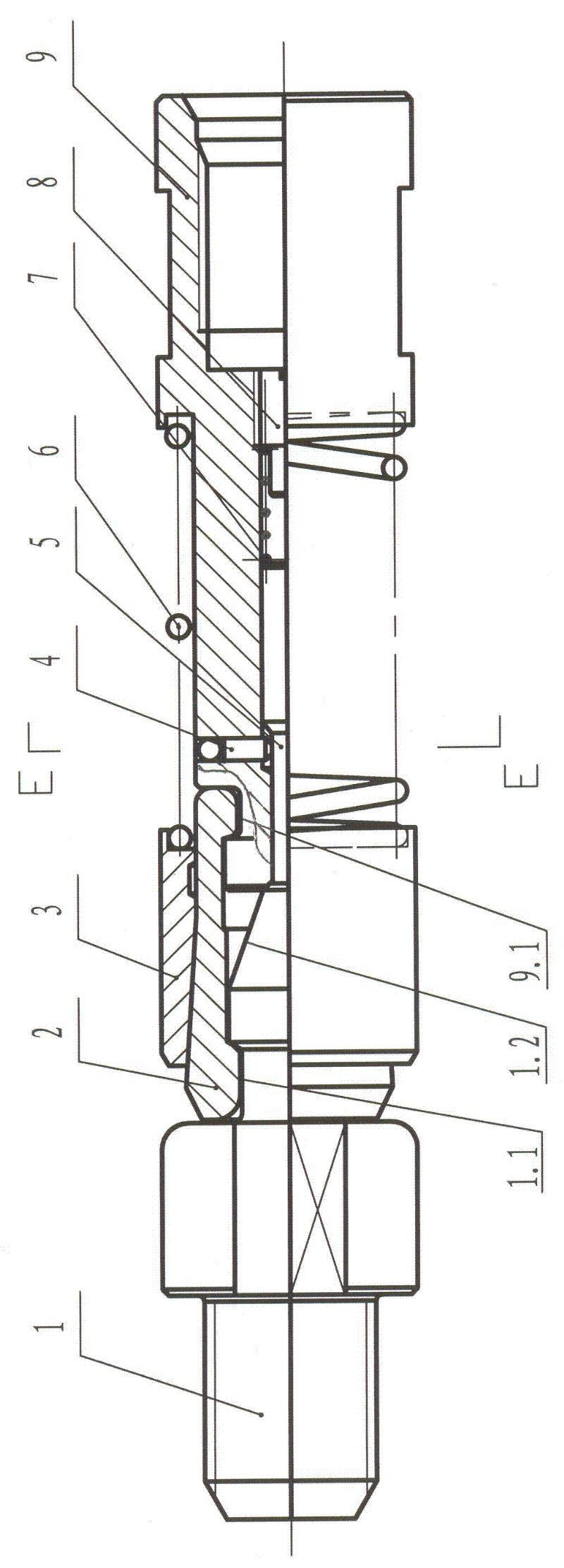
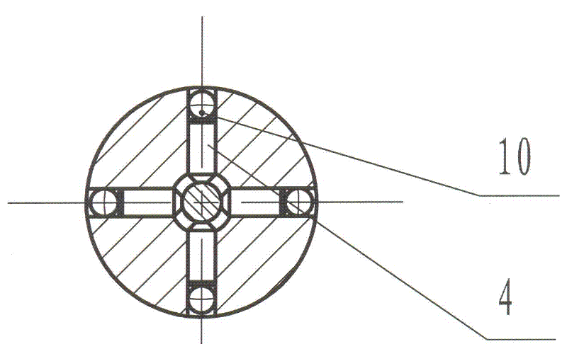
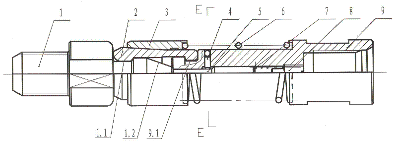
[0011] See figure 1 , 2 , the specific structure is as follows: on the outer sliding sleeve 3 of the limit short-circuit 9, the inner surface of the lock sleeve 3 is provided with an annular lock groove; A large spring 6 is set between the lower end faces of the cover 3; a spring seat 8 and a lock bar 5 are fixedly assembled in the inner hole of the limit short circuit 9, and a small spring 7 is arranged between the spring seat 8 and the lock bar 5; The thin section of the part and the thick section of the lower part are composed; the ejector rod 4 is assembled along the circumference on the limit short connection 9, the outer end of the ejector rod 4 is provided with a steel ball 10, and the inner end of the ejector rod 4 is pressed against the surface of the locking rod 5, The steel ball 10 contacts the annular lock groove of the lock sleeve 3; the upper end of the limit short 9 is provided with an annular lock groove 9.1, the upper end of the center rod 1 has an external t...


PUM


Abstract

The invention discloses a high-intensity small pump uncoupling device which comprises a central rod and a limit pup joint, wherein the upper end part of the central rod is provided with an external thread; the outer part of the limit pup joint is slipperily sleeved with a lock sleeve, the peripheral surface of the limit pup joint is provided with a stop opening, and a large spring is arranged between the stop opening on the peripheral surface of the limit pup joint and the lower end face of the lock sleeve; a spring seat and a lock rod are fixedly assembled in an inner hole of the limit pup joint, and a small spring is arranged between the spring seat and the lock rod; the lock rod is composed of a thin section at the upper part of the lock rod and a thick section at the lower part of the lock rod; a roof rod is circumferentially assembled on the limit pup joint, the outer end of the roof rod is provided with a steel ball, the inner end of the roof rod is pressed against the surface of the lock rod, and the steel ball is in contact with the lock sleeve; and the upper end of the limit pup joint is provided with a ring lock groove, the lower end of the central rod is provided with a guide cone, the upper end of the guide cone is provided with an angle ring groove, an upper internal boss and a lower internal boss are arranged on a split butt-jointed claw of which the outside surface is provided with a taper, the upper internal boss is surrounded in the angle ring groove, and the lower internal boss is surrounded in the ring groove at the upper end of the limit pup joint. The uncoupling device disclosed by the invention is suitable to be applied to the connection of multistage small pumps, is simple in structure, high in strength, easy to operate, reliable in performance, and is capable of improving the oil pumping quantity and prolonging the service life.

Description

technical field [0001] The invention belongs to an oil field oil production machine, in particular to a high-strength small pump disconnector. Background technique [0002] At present, the production process of multi-stage oil pumps is used in oil production plants in oil fields to improve oil recovery efficiency. However, due to the small amount of oil in the formation of some oil wells, multi-stage small pumps are required to operate. Since the multi-stage small pumps cannot be connected on the ground The docking process needs to be completed downhole. The existing problem is that the original connecting tool for connecting the sucker rod and the pump piston is not suitable for small pumps. Therefore, it is necessary to provide a high-strength small pump disconnector to complete the connection between the sucker rod and the pump piston. Contents of the invention [0003] The purpose of the present invention is to provide a high-strength small pump disconnector, suitable ...

Claims


Application Information

Patent Timeline
Patent Type & Authority Applications(China)
IPC IPC(8): E21B17/02
Inventor 梁伟成梁闯
Owner 梁伟成
Learn More