Eureka AIR delivers breakthrough ideas for toughest innovation challenges, trusted by R&D personnel around the world.

Anti-collision circuit of RFID (Radio Frequency Identification Device)tag and realizing method thereof

A technology of RFID tags and implementation methods, applied to record carriers, instruments, computer parts, etc. used in machines, can solve the problems of restricting the performance of RFID tag chips, increasing the area of ​​hardware circuits, reducing chip manufacturing costs, and saving chips. Circuit area, reduction in the number of registers used, effect of reducing power consumption

Inactive Publication Date: 2012-04-11
GUANGZHOU SYSUR MICROELECTRONICS
View PDF4 Cites 5 Cited by
  • Summary
  • Abstract
  • Description
  • Claims
  • Application Information

AI Technical Summary

Problems solved by technology

However, such a design, due to the use of a large number of registers, increases the area of ​​the hardware circuit. When performing operations such as data transmission, all the registers in the register group will be flipped at the same time, which will generate a huge transient power consumption.
However, chip circuit area and power consumption are two important factors of RFID tag chips. Therefore, the design of traditional RFID tag chip anti-collision hardware circuits greatly restricts the improvement of RFID tag chip performance and chip manufacturing. cost reduction

Method used


Image

  • Anti-collision circuit of RFID (Radio Frequency Identification Device)tag and realizing method thereof
  • Anti-collision circuit of RFID (Radio Frequency Identification Device)tag and realizing method thereof
  • Anti-collision circuit of RFID (Radio Frequency Identification Device)tag and realizing method thereof

Examples


Embodiment Construction

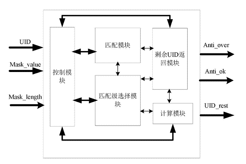
[0029] refer to figure 1 , An anti-collision circuit for an RFID tag provided in Embodiment 1 has three signal input terminals and three signal output terminals (necessary signal terminals such as power supply, reset and clock are ignored). The input signals are: UID value, mask value (Mask_value) and mask length value (Mask_length). The output signals are: matching end signal value (Anti_over), matching result value (Anti_ok) and remaining UID value (UID_rest). When the matching operation ends, Anti_over is set to 1, generating a positive pulse to inform the external logic that the matching operation has been completed. If the match is successful, Anti_ok is set to 1, and at the same time, the value of UID_rest is updated. If the match fails, Anti_ok is cleared, and UID_rest is cleared at the same time.

[0030] The internal circuit structure includes a control module, a matching module, a matching level selection module, a remaining UID return module and a calculation mod...


PUM


Abstract

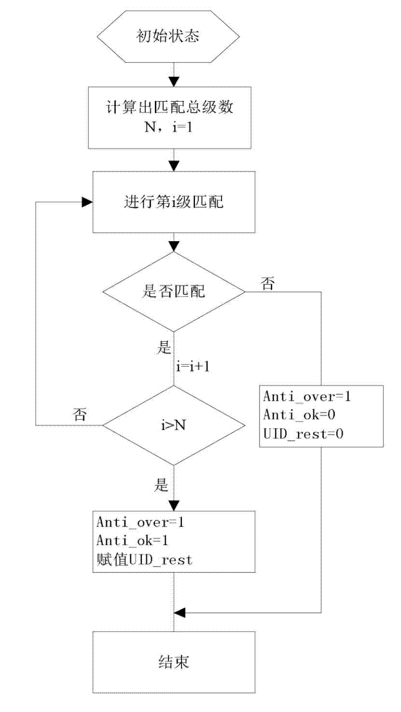
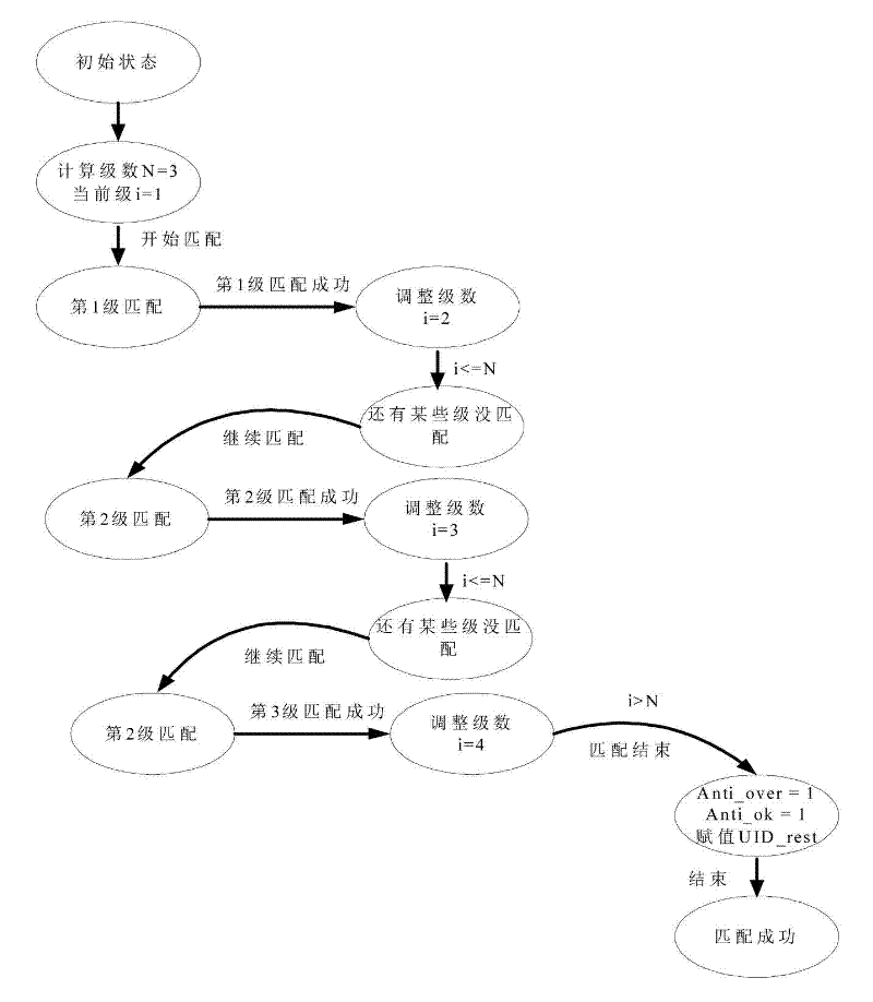
The invention discloses an anti-collision circuit of RFID (Radio Frequency Identification Device)tags and a realizing method thereof. The anti-collision circuit comprises three signal input terminals of UID (User Interface Design) values, mask values and mask length values, three signal input terminals of matching ending signal values, matching result values and residue UID values, and a control module, a matching module, a matching level selecting module, a residue UID return module and a calculating module. The realizing method comprises: according to the mask length values and a preset matching level number, calculating the total level number that the UID values match with the mask values; regarding the matching level number as a basic unit number, selecting a value of a basic unit number from both the UID values and the mask values successively for carrying out multi-level matching comparison. By adopting a method of multi-level matching to the UID values, the circuit in the invention reduces the numbers of registers used in the anti-collision circuit of the RFID tag, so that not only the area of a chip circuit is saved but also the number of registers which are turned over simultaneously is reduced, thereby reducing energy consumption of the chip circuit of the RFID tag greatly. The circuit in the invention is applicable in RFID system field.

Description

technical field [0001] The invention relates to an anti-collision circuit and a realization method thereof, in particular to an anti-collision circuit of an RFID tag and a realization method thereof. Background technique [0002] RFID, radio frequency identification technology is a non-contact automatic identification technology. An RFID system consists of readers, tag chips, antennas and middleware. When multiple electronic tags enter the sensing area of ​​one or more readers, the simultaneous communication between the reader and multiple tags will cause the wireless communication signals to interfere with each other, so that the reader cannot receive correct information. This situation is called called "conflict". In order to avoid the impact of conflicts, the RFID system defines a series of operations when conflicts occur, so as to selectively operate on a single electronic tag. [0003] The anti-collision circuit of the RFID tag chip is the core part of the RFID syste...

Claims


Application Information

Patent Timeline
Patent Type & Authority Applications(China)
IPC IPC(8): G06K19/073
Inventor 王德明郑俊辉陈宇丁一胡建国谭洪舟
Owner GUANGZHOU SYSUR MICROELECTRONICS
Why Eureka
Eureka Blog
Learn More