Wavelength division-time division hybrid passive optical network system

A technology of passive optical network and optical network unit, which is applied in the field of high-speed and large-capacity wavelength-division time-division hybrid passive optical network system, and can solve the problems of high price, limited application, and limited number of scalable users.

Inactive Publication Date: 2012-04-11
BEIJING UNIV OF POSTS & TELECOMM
View PDF4 Cites 10 Cited by
  • Summary
  • Abstract
  • Description
  • Claims
  • Application Information

AI Technical Summary

Problems solved by technology

However, optical network units based on RSOA or injection-locked FP lasers require optical line terminals to provide high-power seed ASE (amplified spontaneous emission, Amplified Spontaneous Emission) light sources or distributed feedback lasers, which limits the number of scalable users
Although the optical network unit based on tunable lasers does not have the above problems, its high price limits its application in WDM and TDM passive optical network systems

Method used


Image

  • Wavelength division-time division hybrid passive optical network system
  • Wavelength division-time division hybrid passive optical network system
  • Wavelength division-time division hybrid passive optical network system

Examples


no. 1 Embodiment

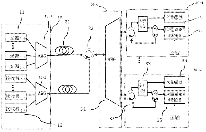
[0023] First, refer to figure 1 The wavelength division time division hybrid passive optical network system according to the first embodiment of the present invention will be described. In this embodiment, the injection light may be light emitted by a downlink single-wavelength light source at the central office.

[0024] figure 1 It is a block diagram showing a specific configuration of the wavelength division time division hybrid passive optical network system according to the first embodiment of the present invention. Such as figure 1 As shown, the wavelength division time division hybrid passive optical network system includes a central office 10, a plurality of optical network units 20-1, ..., 20-N, and a plurality of optical network units 20-1, ... 20-N located between the central office 10 and the plurality of optical network units 20-1, ... The remote node 30 of N.

[0025] Among them, the central office 10 includes a device for generating 1 , lambda 2 ,...λ NA ...

no. 2 Embodiment

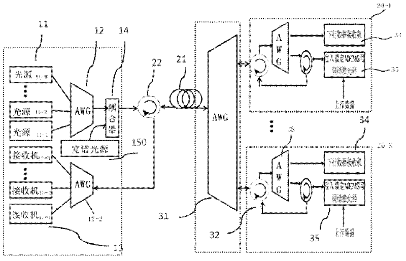
[0033] Next, refer to figure 2 A wavelength division time division hybrid passive optical network system according to a second embodiment of the present invention will be described. In this embodiment, the injected light may be light emitted by a downlink broadband light source at the central local end.

[0034] figure 2 It is a block diagram showing a specific configuration of a wavelength division time division hybrid passive optical network system according to the second embodiment of the present invention. The wavelength-division / time-division hybrid passive optical network system related to the second embodiment has a structure similar to that of the first embodiment, and the same reference numerals are assigned to the same constituent elements as those of the first embodiment, and detailed description thereof is omitted. Here, Only the different structural features are described.

[0035] Among them, the central office 10 is equipped with a plurality of light source...


PUM


Abstract

The invention provides a wavelength division-time division hybrid passive optical network system, which comprises a central office, a plurality of optical network units and a remote node, wherein the remote node is positioned between the central office and the plurality of optical network units; the central office is provided with a plurality of light sources for emitting downlink signal light of various wavelengths, a plurality of receivers for receiving uplink signal light emitted by the plurality of optical network units and transmitted by the remote node respectively, and a plurality of multiplexer / demultiplexers for multiplexing and demultiplexing the downlink signal light and the uplink signal light; the remote end node is used for multiplexing the downlink signal light from the central office and demultiplexing the uplink signal light from the optical network units; and each optical network unit is provided with an internal annular coupler, a light separating unit for separating downlink signal light into signal light and injection light, a downlink data receiver for receiving separated signal light, and an MEMS (Micro Electro Mechanical System) tunable laser for receiving injection light and generating uplink signal light.

Description

technical field [0001] The present invention relates to wavelength-division-time-division hybrid passive optical network (WDM-TDM-PON), in particular, relates to utilizing the downlink signal light pair of optical line terminal (OLT, Optical Line Terminal) as optical network unit (ONU, Optical Network Unit) ) light source MEMS (Micro-Electro-Mechanical Systems, Micro-Electro-Mechanical Systems) tunable laser injection-locked high-speed and large-capacity wavelength-division time-division hybrid passive optical network system. Background technique [0002] Passive Optical Network (PON, Passive Optical Network) technology, as a key technology to solve the "last mile" of the access network, has been widely used in fiber-to-the-home (FTTH) systems. The wavelength division time division hybrid passive optical network combines the advantages brought by the optical power distribution of the time division multiplexing passive optical network and the advantages of the wavelength rout...

Claims


Application Information

Patent Timeline
Patent Type & Authority Applications(China)
IPC IPC(8): H04B10/155H04B10/158H04B10/25H04J14/02
Inventor 程远兵伍剑林金桐
Owner BEIJING UNIV OF POSTS & TELECOMM
Why Eureka
Try Eureka