Discharge lamp

A technology for discharge lamps and discharge vessels, which is applied in the manufacture of high-pressure discharge lamps, discharge tubes/lamps, and parts of gas discharge lamps, and can solve problems such as damage

Active Publication Date: 2012-04-11
OSRAM GMBH
View PDF4 Cites 2 Cited by
  • Summary
  • Abstract
  • Description
  • Claims
  • Application Information

AI Technical Summary

Problems solved by technology

Therefore, when the lamp vibrates, for example during transport, vibrations of the electrode rod can be transmitted to the constriction section and cause damage (natural resonance)
In addition, due to the alternating thermal expansion of the electrode rods, friction against the inner wall of the lamp shaft can occur in the constriction section and thus damage it

Method used


Image

  • Discharge lamp
  • Discharge lamp
  • Discharge lamp

Examples


Embodiment Construction

[0018] The same reference numerals are used below to designate the same or the same type of features.

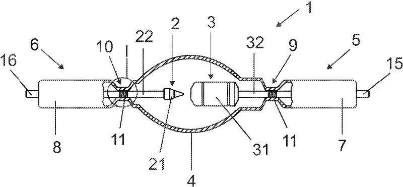
[0019] figure 1 A first embodiment of a short-arc discharge lamp 1 according to the invention is shown in the schematic diagram, which lamp is designed for projection purposes and has an output power of 4000 W. This refers to an inert gas short-arc discharge lamp filled with xenon gas. The lamp 1 is designed for DC operation and has a cathode 2 and an anode 3 for this purpose. The two electrodes 2 , 3 are arranged opposite each other at a distance of approximately 7 mm in an essentially ellipsoidal discharge vessel 4 made of quartz glass and thus define a longitudinal axis A of the lamp. Cathode 2 and cathode 3 each have an electrode tip 21 or 31 and an electrode rod 22 or 32 . The electrode head and the electrode rod are here each separate parts inserted into one another, but can also be produced from a single part. The electrode rods 22 , 32 extend into a respective su...


PUM


Abstract

A discharge lamp (1), comprising two opposing electrodes (2, 3), has at least in the region of an electrode rod (32) a narrower section (9) in the lamp shaft (5) for centering and guiding the corresponding electrode (3). A damping / guiding element, such as a resilient wire helix (11) or an embossed foil, or both, is disposed between the electrode rod (32) and the inside of the narrower section (9) and improves the guiding and damping of the electrode (3), in particular in the case of shocks or vibrations. The risk of damaging the lamp shaft (5) in the region of the narrower section (9) can thus be reduced.

Description

technical field [0001] The invention relates to a discharge lamp. Such lamps are used, for example, for optoelectronic purposes such as projection technology, exposure of semiconductors, hardening with UV rays, etc., but also for general lighting, stage and architectural lighting, etc. Background technique [0002] Such lamps have a discharge vessel filled with a discharge medium, for example an inert gas, with or without mercury additions and possibly other filling additions. Two opposing electrodes are arranged within the discharge vessel, which are each supported by a lamp shaft arranged coaxially to the respective electrode. A gas-tight current lead-out connection for the electrical connection between the external current connection and the electrodes is also provided in the lamp shaft. Such a sealing section of the lamp shaft can be, for example, a graded seal (rod seal; "Graded Seal" in English) by means of a transition glass. However, other lamp sealing processes, ...

Claims


Application Information

Patent Timeline
Patent Type & Authority Applications(China)
IPC IPC(8): H01J9/24H01J61/36H01J61/86
CPCH01J61/36H01J61/30H01J61/86H01J9/247
Inventor 斯文-乌韦·巴克伯恩哈德·鲁赫兰德沃尔夫冈·塞茨克里斯蒂安·威德
Owner OSRAM GMBH
Why Eureka
Try Eureka