
Automatic dust removing device for solar cell assembly

A solar cell and automatic dust removal technology, which is applied in the field of solar technology applications, can solve the problems of lower module output power, high maintenance cost, and lower light transmittance on the module surface, so as to ensure normal output, high degree of automation, and avoid hot spot effect Effect

Inactive Publication Date: 2012-04-18
WORLDWIDE ENERGY & MFG NANTONG
View PDF4 Cites 34 Cited by
  • Summary
  • Abstract
  • Description
  • Claims
  • Application Information

AI Technical Summary

Problems solved by technology

Since the components are installed and used outdoors, they will be affected by many environments. Among them, the dust in the air falls on the components, reducing the light transmittance on the surface of the components, and indirectly weakening the intensity of light irradiating the components, thereby reducing Component output power
[0005] On the other hand, when the solar cell module is irradiated by sunlight, if part of the module or part of the solar cells in the module is shaded to form a dark spot, these dark spots will cause the battery to fail to operate normally, causing the temperature of the solar cell to rise sharply. As a result, the solar cells will have dark spots of burnt out, which will damage the performance of the components and affect the power generation effect of the entire photovoltaic system.
The accumulation of dust on the surface of the solar cell module may cause hot spot effect in the module
[0006] It can be seen that the dust removal maintenance of the components in the photovoltaic power generation system is very important, while the traditional maintenance is manual operation and the work efficiency is low. As the scale of the solar power generation system becomes larger and larger, its maintenance cost will be higher

Method used


Image

  • Automatic dust removing device for solar cell assembly
  • Automatic dust removing device for solar cell assembly
  • Automatic dust removing device for solar cell assembly

Examples


Embodiment Construction

[0018] In order to further understand the technical characteristics and content of the patent of the present invention, the detailed technical description of this patent is as follows in conjunction with the accompanying drawings:

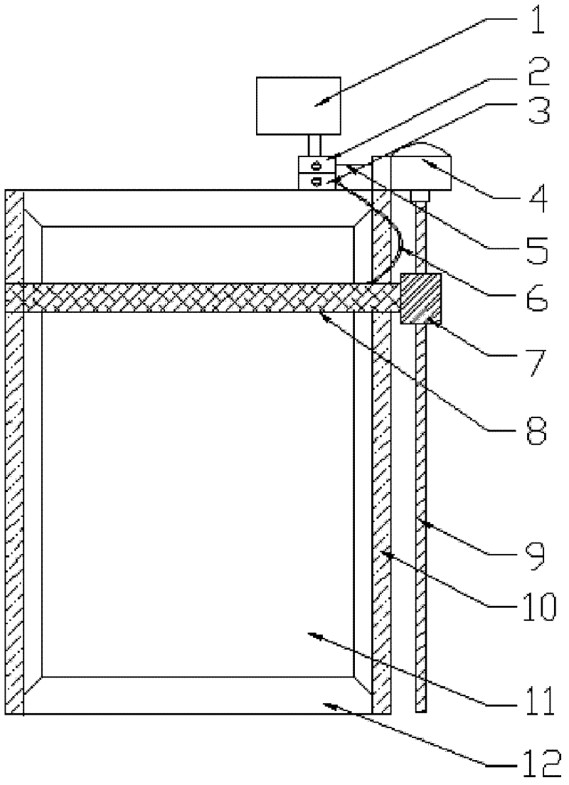
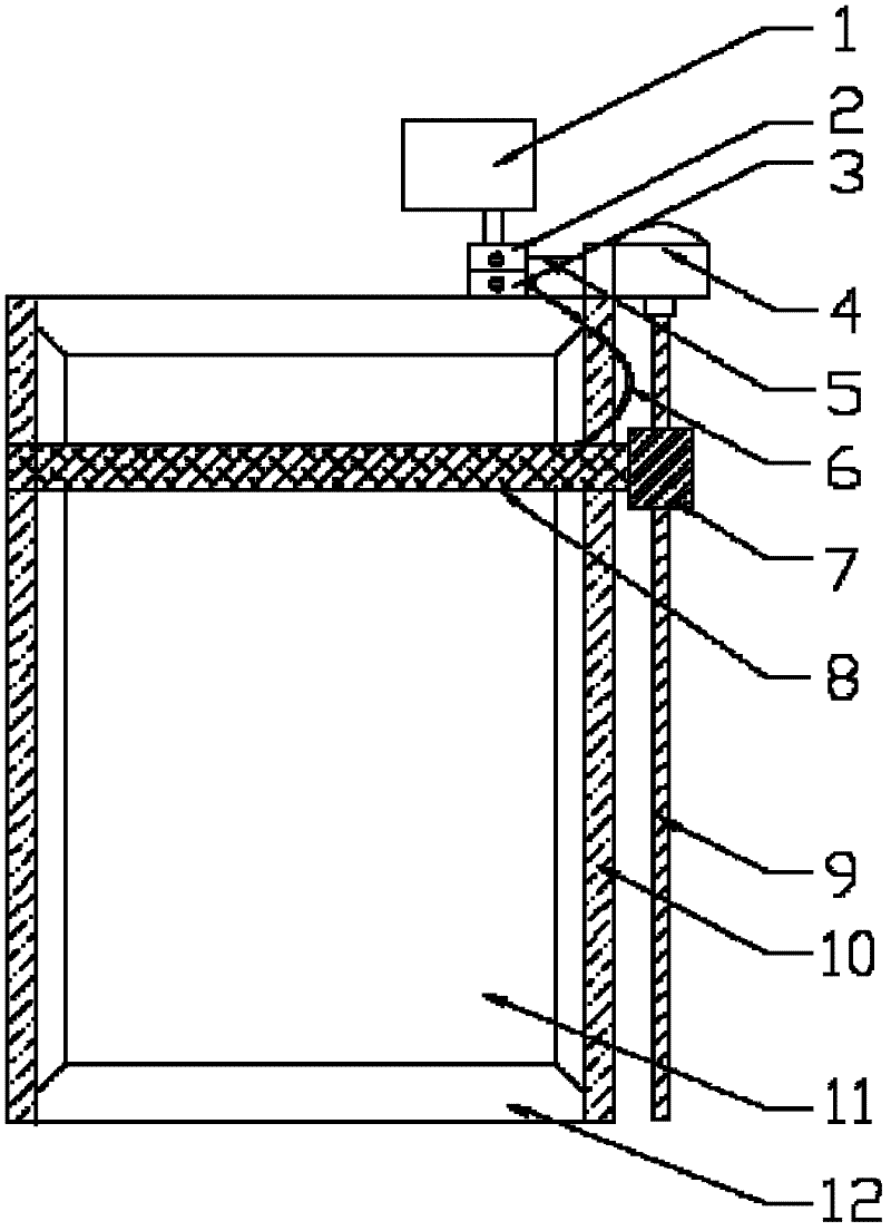
[0019] Such as figure 1 As shown, in the solar cell module automatic dust removal device of the present invention, two linear guide rails 10 are respectively fixed on a group of parallel opposite sides of the frame 12 of the solar cell module; a DC motor 4 is fixed on one end of the frame 12 and connected to a DC motor power supply The switch 2 is connected by a wire 5 . The DC motor 4 is also connected with a ball screw 9, and the ball screw 9 is parallel to the linear guide 10; Nut 7. The DC motor power switch 2 is connected to the external power supply 1. The DC motor power switch 2 controls the opening of the DC motor 4. The rotation of the DC motor 4 makes the nut 7 on the ball screw 9 move up and down, and the electrostatic brush 8 also mov...


PUM


Abstract

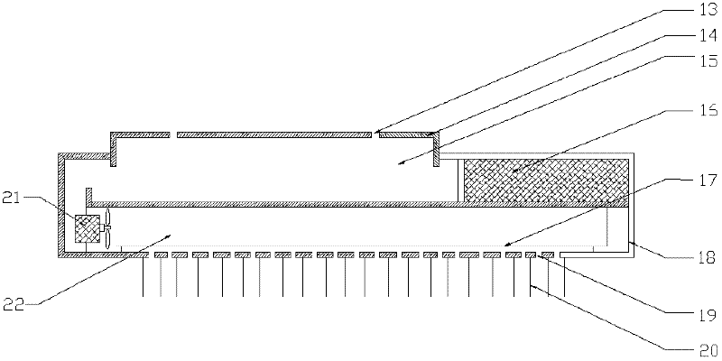
The invention discloses an automatic dust removing device for a solar cell assembly. The dust removing device comprises a direct-current motor power supply switch, a direct-current motor, a ball screw, a linear guide rail and an electrostatic brush, wherein the electrostatic brush comprises an electrostatic generator and fan power supply switch, an electrostatic brush cover, a vent, an electrostatic generator, a fan, an electrostatic net, a dust absorption brush and a dust storage chamber; and the electrostatic brush moves up and down on the surface of the assembly during working and absorbs dust by using electrostatic effect, so that the purpose of removing the dust is fulfilled. The device has high automation degree and high work efficiency, saves a large amount of manpower and material resources, and can effectively remove the dust on the surface of the assembly so that the solar radiation intensity on the surface of the assembly is maximum and normal power output of the assembly is ensured; and through the device, hot spot effect in the assembly can be avoided, the assembly is protected, and the service life of the assembly is prolonged.

Description

technical field [0001] The invention relates to the application field of solar energy technology, in particular to an automatic dust removal device for solar cell components. Background technique [0002] In the 21st century, the energy consumption caused by global economic growth has reached an unprecedented level, and human society is facing a serious situation of fossil fuel shortage and ecological environment pollution. Conventional fossil fuel energy has not only been stretched to meet the development of human society, but also global warming and ecological environment deterioration caused by excessive consumption of fossil fuels have brought greater threats to human survival. Therefore, the sustainable development of energy and environment has become one of the major issues of human concern. To solve this major issue, human beings must find a new energy source. From a long-term point of view, among various renewable energy technologies, solar photovoltaic power gener...

Claims


Application Information

Patent Timeline
Patent Type & Authority Applications(China)
IPC IPC(8): B08B11/00
Inventor 王建军宁兆伟冯涛梁丛武张健超黄涛华周义
Owner WORLDWIDE ENERGY & MFG NANTONG
Learn More