Handheld four-travel engine lubrication system

A four-stroke engine and lubricating system technology, applied in the field of lubricating systems, can solve the problems of poor working reliability, uneven pressure distribution, cumbersome assembly, etc., and achieve the effects of less lubricating oil loss, smooth breathing and ventilation, and stable and reliable work.

Active Publication Date: 2013-03-13
XINGYUE GROUP
View PDF4 Cites 0 Cited by
  • Summary
  • Abstract
  • Description
  • Claims
  • Application Information

AI Technical Summary

Problems solved by technology

[0003] However, the hand-held four-stroke engine has the following defects during use: First, during the working process of the engine, in order to ensure that the various systems such as the crankshaft, connecting rod, piston mechanism, and gas distribution mechanism operate reliably under any working posture, it must be configured to enable lubrication. A lubricating system with high-efficiency oil circulation, but the existing lubricating system is too tortuous, complex in structure, cumbersome in assembly, and difficult in production and processing, which leads to the inability of the lubricating oil to be transported to each working room quickly and unimpeded, reducing to a certain extent The circulation efficiency of lubricating oil; the second is that when the engine is turned over randomly, due to the unsatisfactory oil-gas separation and the poor circulation of the lubrication system, the pressure distribution in the oil return passage inside the lubrication system is uneven, the work reliability is poor, and the oil consumption is large. affect the efficiency of the engine
For this reason, many manufacturers and people of insight develop and develop at the above-mentioned defectives, but so far there is no ideal product in the world.

Method used


Image

  • Handheld four-travel engine lubrication system
  • Handheld four-travel engine lubrication system
  • Handheld four-travel engine lubrication system

Examples


Embodiment Construction

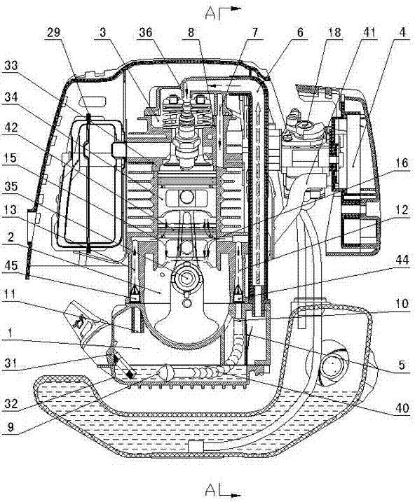
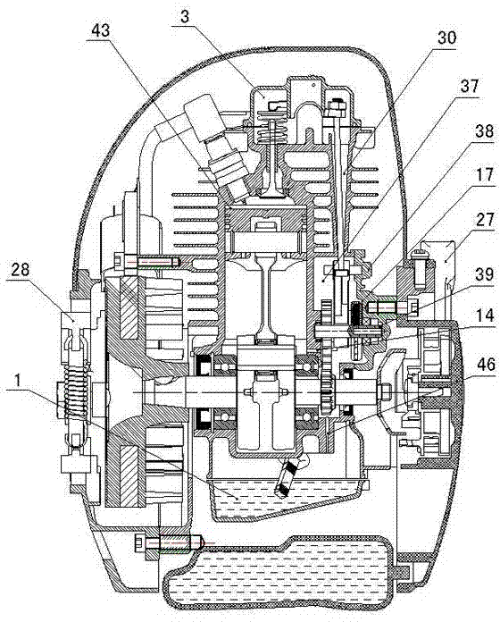
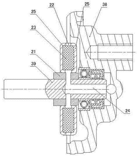
[0025] Figure 1 to Figure 6 As shown, the present invention creates a specific embodiment of a hand-held four-stroke engine lubrication system, which includes the oil storage chamber 1 formed by the bottom case 32 and the lower case 31, the crank chamber formed by the lower case 31 and the upper case 33 2. The valve chamber 3 formed by the upper case body 33 and the cylinder head cover 36, the cam chamber 37 formed by the upper case body 33 and the cam chamber cover 38, the tappet chamber 30 connecting the valve chamber 3 and the cam chamber 37, and the crank chamber A crankshaft connecting rod assembly 32 and a piston 34 are installed in the 2, and the carburetor 18 is connected to the oil tank. The upper and lower boxes 33, 31 are correspondingly provided with first and second inlets connecting the oil storage chamber 1 and the crank chamber 2. Oil passages 12, 13, the first and second oil inlet passages 12, 13 are provided with first and second one-way valves 44, 45 corres...


PUM


Abstract

The invention discloses a handheld four-travel engine lubrication system. The handheld four-travel engine lubrication system comprises an oil storage chamber (1) formed by a bottom case (32) and a lower tank (31), a crank shaft chamber (2) formed by the lower tank (31) and an upper tank (33), a valve chamber (3) which is formed by the upper tank (33) and a cylinder head cover (36), a cam chamber (37), and a tappet rod chamber (30); first and second oil inlet passages (12,13) which are communicated with the oil storage chamber (1) and the crank shaft chamber (2) are correspondingly formed on two sides of the upper and lower tanks (33,31); the first and second oil inlet passages (12,13) are correspondingly provided with first and second check valves (44,45); the first oil inlet passage (12) is connected with a hose (40) which is adhered to the bottom case (32); the head of the hose (40) is provided with a first oil suction port (9); the first oil inlet passage (12) is provided with a second oil suction port (10); and the second oil inlet passage (13) is provided with a third oil suction port (11). Therefore, the handheld four-travel engine lubrication system has the advantages of simple and reasonable structure, high circulation speed, high lubrication efficiency, and the like, and can separate oil and gas well and stably work in any posture.

Description

technical field [0001] The invention relates to a hand-held four-stroke engine, in particular to a lubrication system for the hand-held four-stroke engine. Background technique [0002] With the advancement of science and technology and the rapid development of the economy, the urban and rural areas have taken on a new look, and the living conditions and material living standards of families have been significantly improved. Stroke machines have developed rapidly. Hand-held small engines on the market are mainly based on two-stroke engines that can work in any direction. However, with the enhancement of environmental protection awareness and the continuous improvement of exhaust gas emission requirements, it is an inevitable trend for handheld four-stroke engines to replace handheld two-stroke engines. [0003] However, the hand-held four-stroke engine has the following defects during use: First, during the working process of the engine, in order to ensure the reliable ope...

Claims


Application Information

Patent Timeline
Patent Type & Authority Patents(China)
IPC IPC(8): F01M9/10F01M13/02F01M13/04F02B63/02
Inventor 胡济荣
Owner XINGYUE GROUP
Why Eureka
Try Eureka