Proportional cartridge valve with variable flow gain

A proportional cartridge valve and variable flow technology, used in fluid pressure actuation devices, servo motor components, mechanical equipment, etc., can solve the problem of shortening the service life of hydraulic presses and valves, difficult to ensure linear flow gain, and large pressure and flow impact. and other problems to achieve the effect of improving the flow field characteristics, reducing the vortex area, reducing the pressure shock and the sudden change of speed

Inactive Publication Date: 2012-04-18
YANSHAN UNIV
View PDF5 Cites 19 Cited by
  • Summary
  • Abstract
  • Description
  • Claims
  • Application Information

AI Technical Summary

Problems solved by technology

[0004] However, applying the above-mentioned existing valve components to the pressure relief and unloading control of the forging hydraulic press has common disadvantages: the pressure and flow impact during the pressure relief process is large, and the flow control is not accurate when the flow is small
The main reason is that in the pressure relief and unloading control of the forging hydraulic press, the flow control valve is required to achieve precise control of small flow at a small opening to complete the steady reduction of the main working cylinder pressure. When the main working cylinder pressure drops to a certain value , the flow control valve is required to have a large oil flow capacity to complete the discharge of a large amount of oil in the main working cylinder of the compressor; for valve components with large oil flow capacity, it is difficult to guarantee linearity in the flow gain in the small flow area, and Poor stability leads to poor controllability of the valve at a small opening, which makes the valve components and the front and rear pipelines generate a lot of pressure stamping during the pressure relief process of the main working cylinder, shortening the service life of the hydraulic press and valves

Method used


Image

  • Proportional cartridge valve with variable flow gain
  • Proportional cartridge valve with variable flow gain
  • Proportional cartridge valve with variable flow gain

Examples


Embodiment Construction

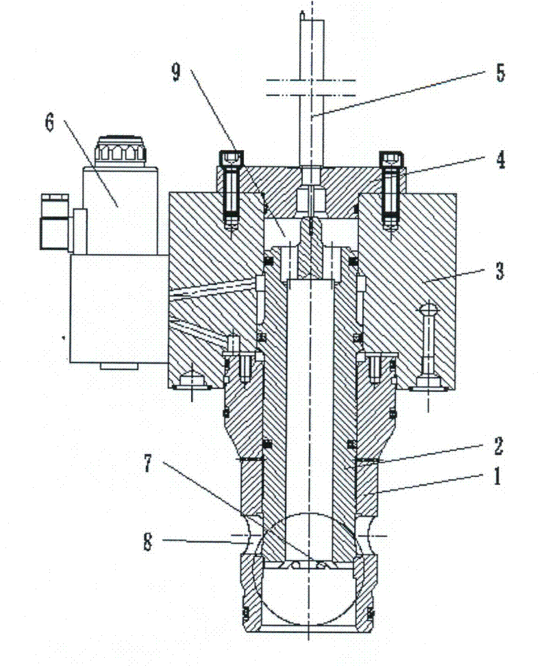
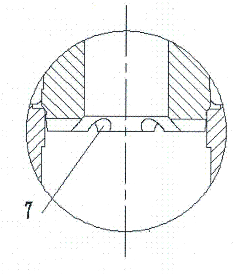
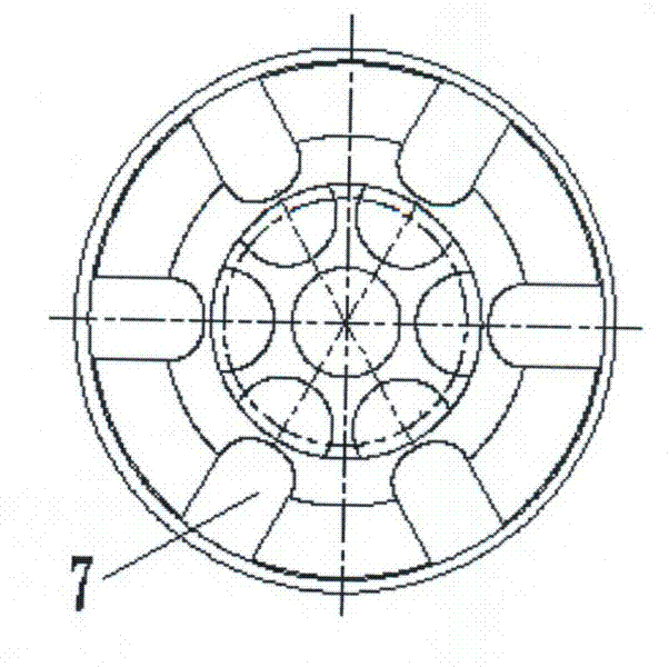
[0015] exist figure 1 In the structural diagram of the proportional cartridge valve with variable flow gain shown, the lower part of the hollow valve core 2 is inside the valve sleeve 1, the lower part of the hollow valve core is sealed with the valve sleeve line, and the upper part of the hollow valve core is matched with the control cover plate 3. The control cover The top of the plate is connected to the bonnet 4, which has a threaded hole, the displacement sensor 5 is fixedly installed on the threaded hole of the bonnet, and the pilot control valve 6 is installed on the side of the control cover plate; a semicircular hole is processed on the port at the bottom of the valve core 7. Make the lower port at the bottom of the valve core a throttling port; four symmetrical waist-shaped holes 8 are arranged on the valve sleeve.

[0016] The working method of the present invention is: the oil flows in from the lower port of the valve core and flows out through the four waist-shape...


PUM


Abstract

The invention discloses a proportional cartridge valve with variable flow gain, which comprises a valve sleeve, a hollow valve core with a damping hole, a control cover plate, a valve cover, a displacement transducer and a pilot control valve, and is characterized in that: the lower part of the hollow valve core is arranged in the valve sleeve and is linearly sealed with the valve sleeve; the upper part of the hollow valve core is matched with the control cover plate; the upper end of the control cover plate is connected with the valve cover; the displacement transducer is arranged on the valve cover; the pilot control valve is arranged on a side face of the control cover plate; a semicircular hole is machined on a port at the bottom of the valve core; and four symmetrical waist-shaped holes are machined on the valve sleeve. The invention has the advantages that: the proportional cartridge valve has small valve opening, low flow gain and high linearity, and high-precision linear control at low flow can be realized; the valve has large valve opening, high flow gain and high linearity, and high-precision linear control at high flow can be realized; and due to low flow fluctuation and low pressure shock of the valve, the service life of the valve can be prolonged.

Description

technical field [0001] The invention relates to a cartridge valve, in particular to an electro-hydraulic proportional cartridge valve. Background technique [0002] With the development of industrial technology, large-scale hydraulic machines such as forging presses, injection molding machines, and die-casting machines are used more and more in China. The control components are very demanding. The proportional throttle valve with cartridge structure has several times the flow capacity of ordinary proportional speed control valves, and has simple structure, low cost, good dynamic and static characteristics and high reliability, which is very important for the realization of system stability and stepless speed regulation. is of great significance. [0003] The working principles of existing electro-hydraulic proportional cartridge valves mainly include displacement-force feedback, displacement-flow feedback, three-stage control type and displacement-electric feedback. Displ...

Claims


Application Information

Patent Timeline
Patent Type & Authority Applications(China)
IPC IPC(8): F15B13/02
Inventor 孔祥东姚静俞滨李亚星
Owner YANSHAN UNIV
Why Eureka
Try Eureka