System for determining SO3 in flue gas

A measurement system and flue gas technology, applied in the field of SO3 measurement system in flue gas, can solve the problems of reduced accuracy and precision, difficulty in SO3 measurement, etc.

Inactive Publication Date: 2012-04-18
PANZHIHUA IRON AND STEEL +2
View PDF2 Cites 30 Cited by
  • Summary
  • Abstract
  • Description
  • Claims
  • Application Information

AI Technical Summary

Problems solved by technology

So far, due to the large excess SO 2 Easily oxidized to high concentration of SO 3 However, the accuracy and precision of the measurement are reduced, so for the SO in complex flue gas 3 The measurement of

Method used


Image

  • System for determining SO3 in flue gas
  • System for determining SO3 in flue gas
  • System for determining SO3 in flue gas

Examples


Embodiment Construction

[0018] Hereinafter, the present invention will be described in detail with reference to specific embodiments of the present invention.

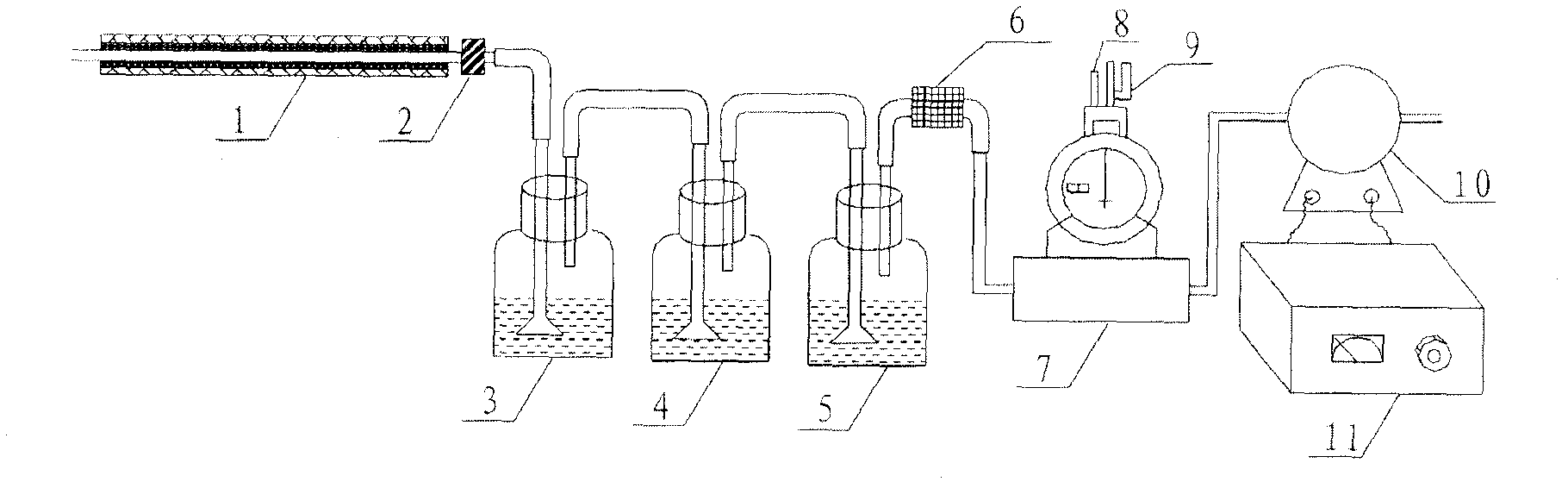
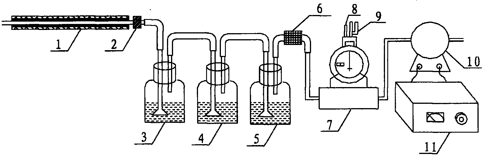
[0019] SO in flue gas according to the present invention 3 The measurement system includes sampler, absorber, gas flow meter and vacuum pump.

[0020] The sampler has a heating function to heat the sampled sintering flue gas to prevent moisture in the sintering flue gas from condensing and absorbing SO in the sintering flue gas 3 , so as to ensure that the SO in the sintering flue gas 3 Assay accuracy and reliability. The absorber is filled with isopropanol aqueous solution with a concentration of 70%-85% and connected to the outlet of the sampler. in isopropanol aqueous solution. To prevent SO 3 The gas is not fully absorbed in the isopropanol aqueous solution, and two or more absorbers can be installed. A gas flow meter is connected to the outlet of the absorber to measure the volume of flue gas. The vacuum pump is connected with the...


PUM


Abstract

The invention discloses a system for determining SO3 in flue gas, comprises the following parts: a sampler which has the function of heating the flue gas that passes through the sampler; an absorber with an aqueous solution of isopropanol, wherein, the inlet of the absorber is connected with the outlet of the sampler to let the flue gas pass through the aqueous solution of isopropanol; a gas flowmeter, wherein, the inlet of the gas flowmeter is connected with the outlet of the absorber; and a vavuum pump which is connected with the outlet of the gas flowmeter.

Description

technical field [0001] The present invention relates to a kind of measuring system of gas, specifically, the present invention relates to a kind of SO in flue gas 3 Determination system. Background technique [0002] The iron and steel industry is one of the industries that cause serious air pollution, and the sintering process is the main source of pollution in the iron and steel industry. In recent years, more and more sinter plants have installed flue gas desulfurization systems to reduce SO emissions 2 , part of the flue gas desulfurization system adopts wet desulfurization process. [0003] Although SO in the sintering flue gas 3 The emissions are relatively small, generally only accounting for 1% to 2% of the total sulfur oxide emissions in the flue gas, but the SO in the sintering flue gas 3 The existence of the presence of the wet flue gas desulfurization will have a greater impact on the operating parameters and operating conditions, especially on the desulfuriz...

Claims


Application Information

Patent Timeline
Patent Type & Authority Applications(China)
IPC IPC(8): G01N5/00G01N1/44G01N1/34
Inventor 王建山黎建明邱正秋张金阳彭良虎邹维嘉罗强罗义文
Owner PANZHIHUA IRON AND STEEL
Why Eureka
Try Eureka