Solar terminal box

A junction box and solar energy technology, applied in the field of solar photovoltaics, can solve the problems of increased junction box cost, limited heat dissipation effect, waste of sealant, etc., achieve good waterproof and dustproof effects, simple and time-saving installation, and prevent thermal expansion.

Inactive Publication Date: 2012-04-18
DONGGUAN ZERUN ELECTRONICS TECH
View PDF9 Cites 23 Cited by
  • Summary
  • Abstract
  • Description
  • Claims
  • Application Information

AI Technical Summary

Problems solved by technology

[0003] In existing solar junction boxes, the diodes are directly installed on the conductive sheet or terminal block inside the box body. Due to the high temperature inside the junction box and the junction of the diodes, the life of the diodes is shortened, and the solar junction box and its components are also increased. The risk of component damage, causing the solar substrate to be significantly heated to reduce work efficiency
In order to solve the above problems, a radiator is directly added to the existing solar junction box, but the problem is that the radiator cannot transfer heat to the outside of the junction box, so the cooling effect is limited, and there is a risk of heat accumulation in long-term use , while increasing the cost of the junction box
The existing solar junction box and the solar substrate are sealed and connected by a sealant. The diode heat dissipation part of the solar junction box is directly attached to the solar substrate, and there is air around the diode. The air cannot be released to the outside, endangering the solar junction box, causing the solar substrate to be significantly heated and reducing work efficiency
[0004] In addition, the existing solar junction box has a large volume, high manufacturing cost, and waste of sealant
Most of the existing solar junction boxes are parallel outlets. When the solar junction boxes are connected, the wires are obviously bent, which is easy to generate stress and even cause the junction box to be not firmly pasted, which affects the overall service life of the solar junction box.

Method used


Image

  • Solar terminal box
  • Solar terminal box
  • Solar terminal box

Examples


Embodiment Construction

[0024] In order to further understand the features, technical means, specific objectives and functions achieved by the present invention, and to analyze the advantages and spirit of the present invention, a further understanding of the present invention can be obtained through the following detailed description of the present invention in conjunction with the accompanying drawings and specific embodiments.

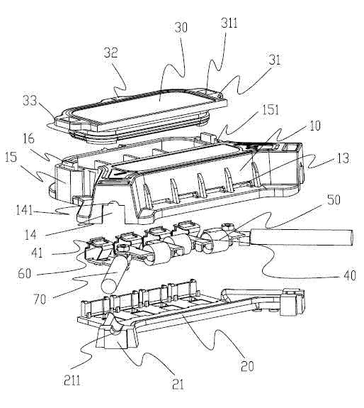
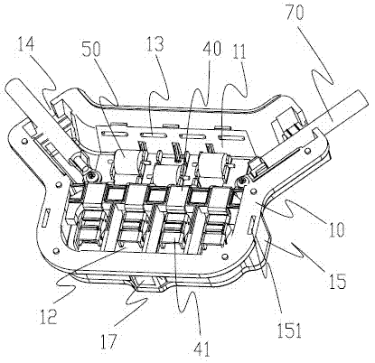
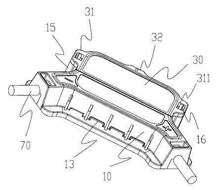
[0025] As shown in the accompanying drawings, the present invention includes a box body 10 , a bottom cover 20 matching the bottom of the box body 10 , and a surface cover 30 fastened to the top of the box body 10 . The bottom cover 20 is fixed to the box body 10 by ultrasonic welding. Both the edge of the bottom of the box body 10 and the middle of the bottom of the bottom cover 20 are provided with a fixing part, and the junction box is fixedly connected to the solar substrate through a sealant. The fixing part is in the shape of a "day", so that the connection between t...


PUM


Abstract

The invention discloses a solar terminal box which is simple in structure and small in volume and comprises a box body, a bottom cover and a surface cover, wherein the bottom cover is matched with the bottom of the box body; the surface cover is bucked on the top of the box body; the box body is provided with a containing space I with an opening facing the bottom cover and a containing space II with an opening facing the surface cover; a wiring terminal and a diode are arranged in the containing space I; the containing space I forms an adhesive pouring area by pouring potting adhesive; an air vent is arranged on the side surface of the box body; the bottom cover is fixed on the box body in an ultrasonic welding manner; outgoing included angles of two electrical cables at two end parts of the box body of the terminal body are right angles; the solar terminal box is simple to install, is welded in an ultrasonic welding process and is firm in structure; a vertical line outgoing manner is adopted in the electrical cables so that when the solar terminal boxes are connected to each other, the bending and the stress of the electrical cables can be reduced; and the bottom of the adhesive pouring area is arranged on a solar substrate in a suspending manner, and the air vent is communicated with the bottom of the adhesive pouring area in a suspending manner, thereby being beneficial to heat dissipation when the diode works.

Description

technical field [0001] The invention relates to the field of solar photovoltaics, in particular to a solar junction box. Background technique [0002] With the rapid development of economic globalization and integration, energy shortage has become an important factor restricting economic development. At present, solar technology is developing rapidly, especially the development of solar power plants, solar building integration and other technologies, especially the electrical connection requirements of solar cell components are getting higher and higher. When connecting, solar junction boxes are often used, and solar junction boxes are used as solar energy The main component of the power supply is widely used in various solar power supplies. [0003] In existing solar junction boxes, the diodes are directly installed on the conductive sheet or terminal block inside the box body. Due to the high temperature inside the junction box and the junction of the diodes, the life of...

Claims


Application Information

Patent Timeline
Patent Type & Authority Applications(China)
IPC IPC(8): H01L31/048H02S40/34
CPCY02E10/50Y02A30/14
Inventor 陈泽鹏
Owner DONGGUAN ZERUN ELECTRONICS TECH
Why Eureka
Try Eureka