
Device for compensating non-linear damage of optical fiber

A technology of nonlinear damage and compensation device, which is applied in the direction of selection device, selection device of multiplexing system, electrical components, etc., can solve the problem of high complexity of optical suppression device

Inactive Publication Date: 2012-04-18
HUAZHONG UNIV OF SCI & TECH
View PDF6 Cites 26 Cited by
  • Summary
  • Abstract
  • Description
  • Claims
  • Application Information

AI Technical Summary

Problems solved by technology

[0005] The invention provides an optical fiber nonlinear damage compensation device, which solves the problem that the transmission rate of the existing electrical suppression device is limited by the digital signal processing speed and the complexity of the optical suppression device is relatively high. transfer rate

Method used


Image

  • Device for compensating non-linear damage of optical fiber
  • Device for compensating non-linear damage of optical fiber
  • Device for compensating non-linear damage of optical fiber

Examples


Embodiment Construction

[0034] The present invention will be further described below in conjunction with the accompanying drawings and embodiments.

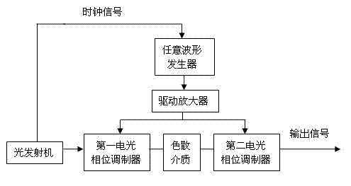
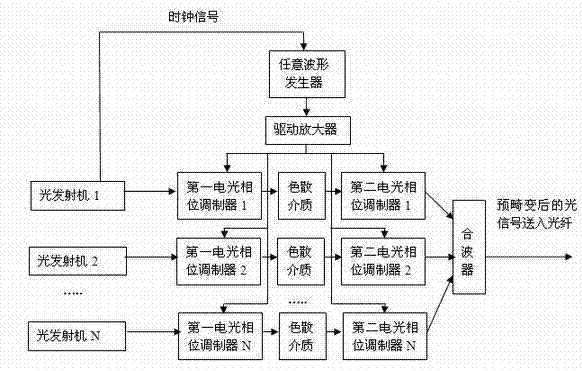
[0035] Such as figure 1 As shown, the embodiment of the present invention includes an arbitrary waveform generator, a driving amplifier, a first electro-optic phase modulator, a dispersive medium and a second electro-optic phase modulator;

[0036] The arbitrary waveform generator and the driving amplifier are serially connected in series, and the output end of the first electro-optic phase modulator is connected to the input end of the second electro-optic phase modulator through a dispersion medium;

[0037] The optical transmitter clock signal from the optical fiber link is input to the trigger terminal of the arbitrary waveform generator, and the arbitrary waveform generator outputs a periodic parabolic waveform signal f(t), and the periodic parabolic waveform signal f(t) is amplified by a drive amplifier to The electric driving signal is sent to t...


PUM


Abstract

The invention discloses a device for compensating a non-linear damage of optical fiber, belongs to an optical fiber communication device, solves the problem of limitation on transmission speed rate or higher complexity of the conventional restraint device, and guarantees the transmission speed rate of an optical fiber system during compensation of the non-linear damage of the optical fiber. The device comprises an arbitrary waveform generator, a driving amplifier, a first electro-optical phase modulator, a dispersion medium and a second electro-optical phase modulator, wherein a clock signal is input to a trigger end of the arbitrary waveform generator; the arbitrary waveform generator outputs a periodic parabola type waveform signal, and the periodic parabola type waveform signal is amplified by using the driving amplifier into an electric driving signal and sent to driving ends of the first electro-optical phase modulator and the second electro-optical phase modulator at the same time; an optical transmitter outputs a data signal to an input end of the first electro-optical phase modulator; and an output end of the second electro-optical phase modulator is connected with an optical fiber link. The invention has the advantages that: an adopted optical device is simple; the bit error rate of signal receiving reaches 10<-7> to 10<-9>; optical power cost is reduced by about 3 dB; and the device is applicable to a long-distance high-capacity and ultra-high-speed optical fiber communication system of all kinds of modulation formats and transmission speed rate.

Description

technical field [0001] The invention belongs to optical fiber communication devices, in particular to an optical fiber nonlinear damage compensation device, which is applied in a high-speed optical fiber communication system to compensate the nonlinear damage in the optical fiber communication system and improve system performance. Background technique [0002] Optical fiber communication has become a basic part of modern communication networks. With the explosive growth of information such as voice, image and data, especially the rapid rise of the Internet, it is an inevitable trend to continuously expand the capacity of optical fiber communication. Wavelength Division Multiplexing (WDM) and Erbium-doped Fiber Amplifier (EDFA) are the best means to fully exploit the bandwidth capability of optical fiber and realize large-capacity and high-speed communication. In high-speed long-distance optical fiber communication systems, 100G and above is the current development trend, an...

Claims


Application Information

Patent Timeline
IPC IPC(8): H04B10/18H04Q11/00H04B10/2543
Inventor 李蔚余少华成浩然
Owner HUAZHONG UNIV OF SCI & TECH
Learn More