Routing method for module-expansion-based data center network topology system

A data center network and basic module technology, applied in the Internet field, can solve problems such as huge routing table entries, lagging routing decision-making, and large system overhead, so as to improve transmission rate and data throughput, improve network transmission efficiency, and realize traffic flow balanced effect

Inactive Publication Date: 2012-04-18
XIDIAN UNIV
View PDF4 Cites 30 Cited by
  • Summary
  • Abstract
  • Description
  • Claims
  • Application Information

AI Technical Summary

Problems solved by technology

The working mechanism of open shortest path first OSPF is not suitable for large-scale data center networks, because collecting network status information has the following defects for data center networks: waste of storage space, collection of status information is not real-time, and routing decisions are relatively lagging; RIP protocol When working, the current device needs to exchange routing table information with its adjacent devices. Because the data center network is large in scale, the routing table entries of each device are huge, which wastes storage space and exchanges routing table information in real time, resulting in high system overhead. , and the update of routing information is relatively lagging behind, which is not conducive to routing decision-making
[0009] The above two routing methods all have the following deficiencies: First, the ECMP and VLB routing methods can only make full use of the equal-cost paths in the network topology, but cannot take advantage of the non-equivalent paths in the topology. Here, the equal-cost paths refer to data

Method used


Image

  • Routing method for module-expansion-based data center network topology system
  • Routing method for module-expansion-based data center network topology system
  • Routing method for module-expansion-based data center network topology system

Examples


Embodiment 1

[0043] Embodiment 1: The source server and the destination server are in the same basic module, and are connected by different edge layer switches in the same Pod structure.

[0044] refer to Figure 4 , the routing method of the present invention, its implementation steps are as follows:

[0045] Step 1. Identify each network device in the topology system.

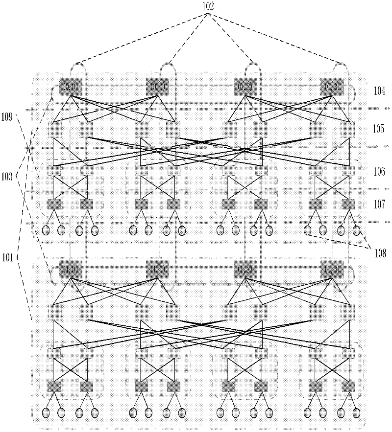
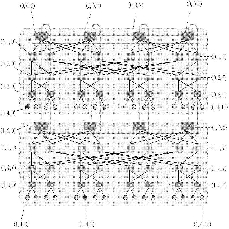
[0046] 1.1) The data center network topology system based on module expansion used by the present invention is as follows: figure 2 , it includes m basic modules, and each basic module includes k Pod structures, where m=2, k=4, but not limited to this value, using three-dimensional coordinates to address each network device in the topology system:

[0047] The address information of the source server S is used (S x , S y , S z ) representation, the address information of the destination server D is represented by (D x ,D y ,D z ) representation, the address information of the core layer switch C is represented by...

Embodiment 2

[0082]Embodiment 2: The source server and the destination server are located in the same basic module, and are connected by edge layer switches in different Pod structures.

[0083] refer to Figure 4 , the routing method of the present invention, its implementation steps are as follows:

[0084] Step 1. is the same as step 1 in the above-mentioned embodiment 1.

[0085] Step 2. is the same as step 2 in the above-mentioned embodiment 1.

[0086] Step 3. is the same as step three in the above-mentioned embodiment 1.

[0087] Step 4. Determine the source and destination servers, and send the data packets generated by the source server to the directly connected edge layer switch.

[0088] 4a) Set the source server S as (0, 4, 4), and the destination server D as (0, 4, 11);

[0089] 4b) The source server generates a data packet, and encapsulates the address information of the destination server into the data packet;

[0090] 4c) According to the address information of the sou...

Embodiment 3

[0126] Embodiment 3: The source server and the destination server are in different basic modules.

[0127] refer to Figure 4 , the routing method of the present invention, its implementation steps are as follows:

[0128] Step A. is the same as step one in the above-mentioned embodiment 1.

[0129] Step B. is the same as step two in the above-mentioned embodiment 1.

[0130] Step C. is the same as step two in the above-mentioned embodiment 1.

[0131] Step D. Determine the source and destination servers, and send the data generated by the source server to the directly connected edge switch.

[0132] D1) Let the source server S be (0, 4, 0), and the destination server D be (1, 4, 5);

[0133] D2) The source server generates a data packet, and encapsulates the address information of the destination server into the data packet header;

[0134] D3) According to the address information of the source server S: S z =0=k 2 / 4*i+k / 2*j+p, get the intermediate variable i=0, j=0, ...


PUM


Abstract

The invention discloses a routing method for a module-expansion-based data center network topology system, and mainly aims to solve the problem that the conventional routing methods in the Ethernet and a data center tree network cannot be well applied to the module-expansion-based data center network topology system. The method is implemented by the following steps of: (1) performing initialization, and identifying each piece of network equipment in the topology system by adopting a hierarchical addressing mechanism; (2) reading the addressing information of current network equipment, and judging the type of the current network equipment; (3) generating data, and transmitting the data to edge layer switches by using a source server; (4) determining data output ports according to the destination address of the data and a port with the data by using the edge layer switches, convergence layer switches and intermediate layer switches; and (5), determining a data output port according to the destination address of the data, the hop number of a path hop number and the cache information of the port by using core layer switches. The method has the advantages that: network throughput is improved; traffic balancing is realized; the method can be used for the path selection of a data center network and the provision of high-efficiency data transmission service; and the shortcomings of static routing are overcome.

Description

technical field [0001] The invention belongs to the technical field of the Internet, and in particular relates to a routing method of a data center network topology system based on module expansion, which can be used to realize efficient communication between data center network servers. Background technique [0002] With the rapid development of network and information technology, the data center has become the service center of scientific research institutes, financial institutions and other industries in modern society, carrying the core business of enterprises and meeting the service requirements of data mining, storage, high-performance computing and so on. Therefore, the construction of a data center suitable for the development needs of enterprises has become a key IT construction project for service operators, scientific research institutes, and various portal websites to achieve the purpose of improving service efficiency, reducing operating costs, and improving cent...

Claims


Application Information

Patent Timeline
IPC IPC(8): H04L12/56H04L45/02
Inventor 顾华玺年秀梅王琨赵彦
Owner XIDIAN UNIV
Why Eureka
Try Eureka