Method and apparatus for estimating clutch friction coefficient

A clutch, clutch pressure technology, applied in clutches, mechanical equipment, components with teeth, etc., can solve problems such as inaccuracy, affecting transmission capacity estimation, engine error, etc.

Inactive Publication Date: 2012-04-18
GM GLOBAL TECH OPERATIONS LLC
View PDF5 Cites 7 Cited by
  • Summary
  • Abstract
  • Description
  • Claims
  • Application Information

AI Technical Summary

Problems solved by technology

However, this method has significant disadvantages: arbitrary errors and inaccuracies in the engine will affect the transmission capacity estimate
Since the transfer torque is the difference between the total torque obtain

Method used


Image

  • Method and apparatus for estimating clutch friction coefficient
  • Method and apparatus for estimating clutch friction coefficient
  • Method and apparatus for estimating clutch friction coefficient

Examples


Embodiment Construction

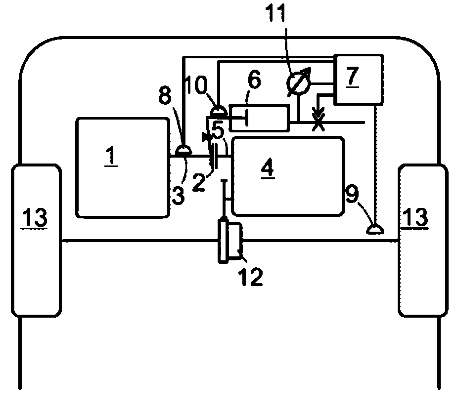
[0019] figure 1 is a schematic top view of the front part of a motor vehicle comprising a combustion engine 1, a clutch 2 for connecting the output shaft 3 of the combustion engine to the input shaft 5 of the transmission 4, a clutch 2 for controlling the opening and closing of the An actuator 6 (such as a hydraulic cylinder), an electronic transmission controller 7 for controlling the clutch 2 via the actuator 6 and the shift forks (not shown) of the transmission 4 via other actuators (not shown) .

[0020] The controller 7 has connected to it a rotational speed sensor 8 for monitoring the rotational speed of the output shaft 3, a speedometer 9, and an actuator controller sensor such as a Hall sensor 10 for monitoring the piston of the actuator 6. The displacement, or the pressure sensor 11, is used to monitor the hydraulic pressure in the cylinder of the actuator 6).

[0021] Reference numeral 12 denotes a differential driven by an output pinion of the transmission 4, and ...


PUM


Abstract

A method for estimating a transmissibility of a clutch in a vehicle powertrain, comprises the steps of : a) cutting off fuel supply of an engine driving a first side of the clutch, b) setting a clutch pressure between first and second sides of the clutch to a positive value at which there is a non-zero difference between angular accelerations at the first and second sides of the clutch (S3, S4), c) deriving said estimated transmissibility from a deviation between said angular acceleration difference and an angular acceleration caused by a drag torque of the engine (S7).

Description

technical field [0001] The present invention relates to a method for estimating the coefficient of friction of a clutch in a vehicle powertrain, and to a vehicle powertrain using the method. Background technique [0002] Accurate knowledge of the friction coefficients of matching clutch surfaces is important for automatic control of clutches in a power train, for example, to control the pressure applied to the first and second sides of the clutch so that a predetermined desired torque can be transmitted, predicted at a predetermined The time required to synchronize the first and second sides of the clutch under pressure and thereby control the shifting process. The torque transfer capability of a clutch in a vehicle powertrain depends on various quantities that may vary between different powertrains. Due to manufacturing tolerances of the clutches and their surrounding components such as the actuators used to drive the clutches open and close, the clutches The temperature a...

Claims


Application Information

Patent Timeline
IPC IPC(8): F16D48/06
CPCF16D2500/3068F16D2500/3063F16D2500/50684F16D48/06F16D2500/3069F16D2500/508F16D2500/30406F16D2500/30402F16D2500/70605F16H2059/186F16H2342/044B60W10/02B60W10/06
Inventor G.汉根
Owner GM GLOBAL TECH OPERATIONS LLC
Why Eureka
Try Eureka