Method and thermal field for growing ingot polycrystal silicon by adopting directional solidification method

A directional solidification, polycrystalline silicon technology, applied in the direction of crystal growth, single crystal growth, single crystal growth, etc., can solve the problems of convex center, affecting crystal quality, large radial temperature gradient, etc., to reduce energy consumption and improve crystal quality , the effect of reducing thermal stress

Inactive Publication Date: 2012-04-25
TRINASOLAR CO LTD
View PDF4 Cites 11 Cited by
  • Summary
  • Abstract
  • Description
  • Claims
  • Application Information

AI Technical Summary

Problems solved by technology

During the crystal growth process of Jinggong Polycrystalline Furnace, the side wall of the heat preservation chamber is fixed, the bottom plate moves down, the distance between the heat dissipation window and the ingot block is relatively large, and the heat dissipation around the opening causes the heat dissipation intensity of the center to be much greater than that of the edge, causing the center of the crystal growth interface to be convex. , the radial temperature gradient in the crystal is large, and the thermal stress will produce too many crystal defects, which will affect the quality of the crystal

Method used


Image

  • Method and thermal field for growing ingot polycrystal silicon by adopting directional solidification method
  • Method and thermal field for growing ingot polycrystal silicon by adopting directional solidification method
  • Method and thermal field for growing ingot polycrystal silicon by adopting directional solidification method

Examples


Embodiment 1

[0018] The zero point is set at 25 cm below the graphite-assisted clot.

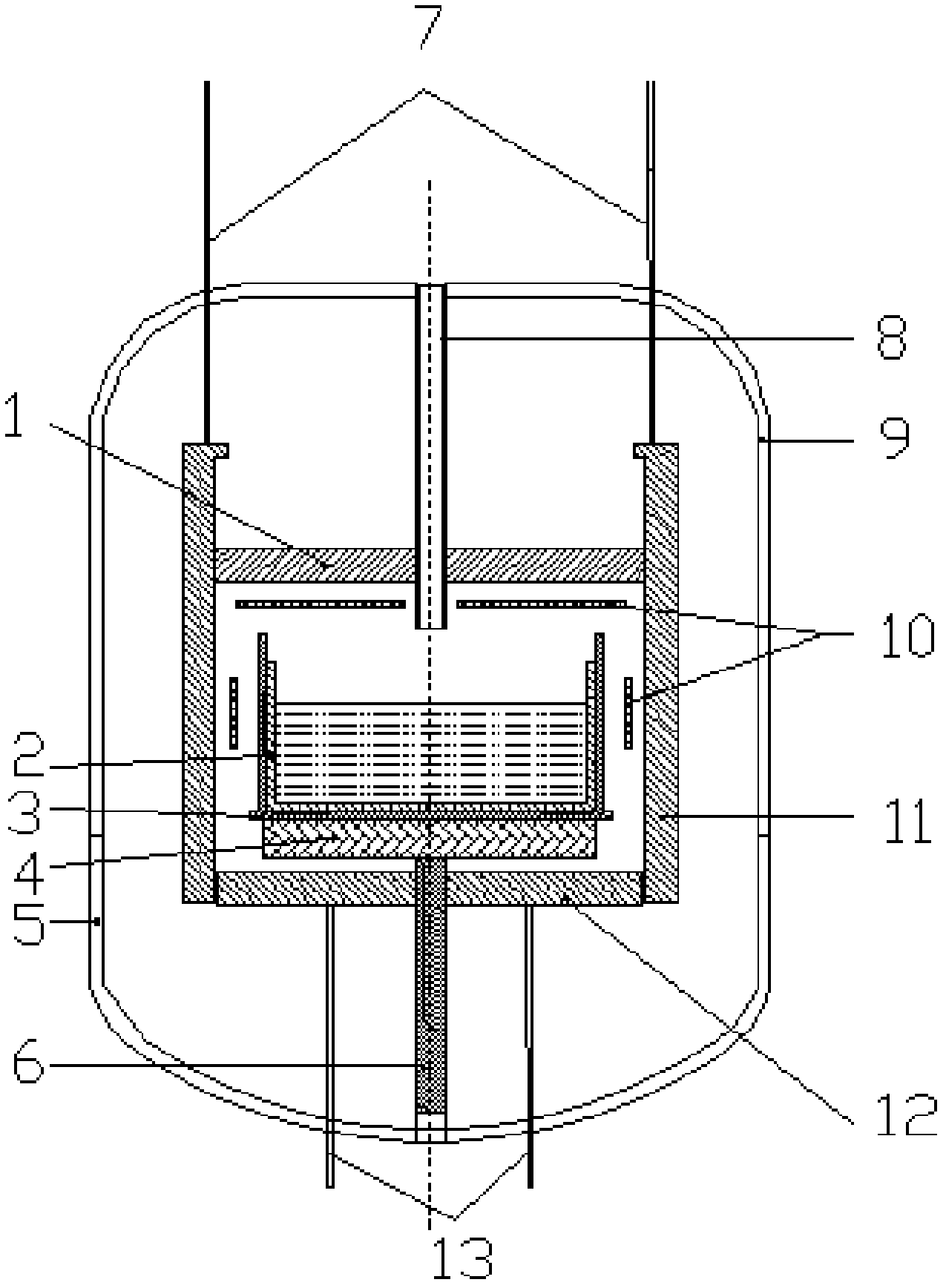
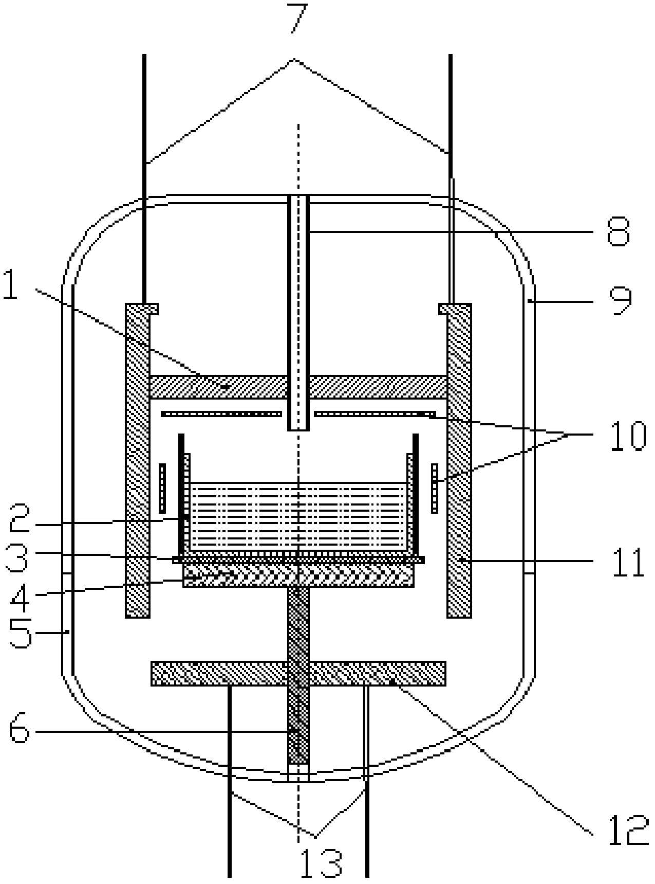
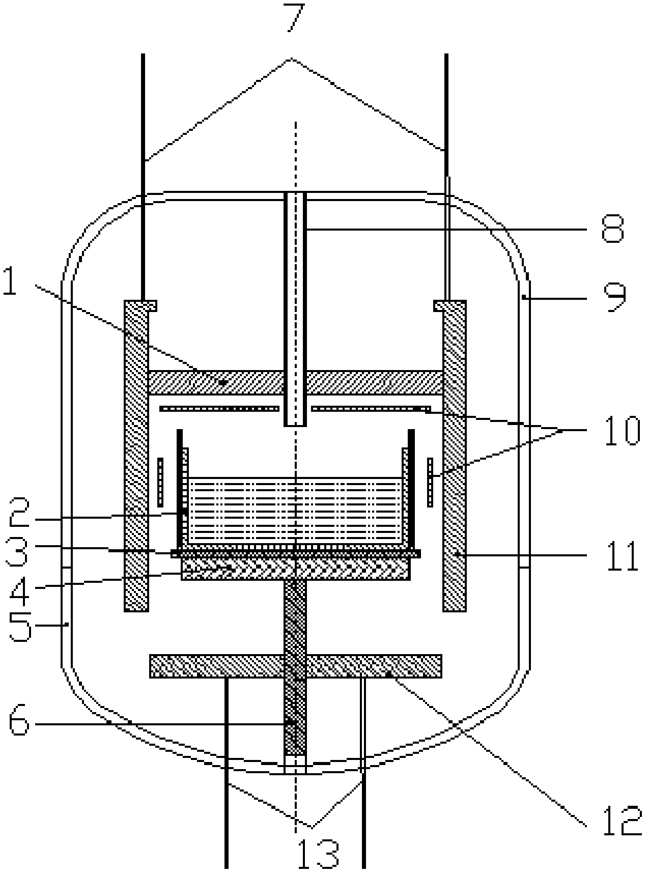
[0019] 1) Before melting: the bottom plate of the heat preservation chamber and the side wall of the heat preservation chamber move up at the same time, and the two remain closed. The distance between the bottom plate of the heat preservation chamber and the graphite coagulation aid is 5cm; Help the space between the clots, so that the high-temperature melting stage, the high-temperature space is reduced to reduce heat dissipation, and achieve the effect of energy saving;

[0020] 2) Melting at high temperature, 0.5 hours after the melting is completed; the bottom plate of the heat preservation cavity and the side wall of the heat preservation cavity move down to zero at the same time; the distance between the bottom plate of the heat preservation cavity and the graphite coagulation aid is opened. Form a cold spot and form large-sized grains that expand from the center to the surroundings;

[0021] 3) C...

Embodiment 2

[0040] Take the closed position of the melting stage as the zero point.

[0041] Process step is similar to embodiment 1, no longer enumerates in detail here, and concrete process parameter is as shown in table 2:

[0042] stage

[0043] The test results show that under the same charging amount, the melting and annealing stage can save 316kwh of electricity, which is about 21% lower than that of the same period last year. Under the same battery process, the conversion efficiency of the silicon wafer is increased by 0.12 percentage points.


PUM


Abstract

The invention relates to a method and a thermal field for growing ingot polycrystal silicon by adopting a directional solidification method. The method comprises the following steps of melting, crystallizing, annealing and cooling. The heat insulation cavity in the ingot polycrystal thermal field consists of a top plate, side walls and a bottom plate, wherein the top plate is fixedly positioned; the side walls and the bottom plate can move up and down; and the distance between each side wall and the bottom plate is controlled according to the requirements of different stages in a crystal growth process. The invention has the advantages that: the power consumption in the material meting process is reduced, and the effect of saving power is achieved; and the movement distance of the bottom plate and each side wall of the heat cavity is respectively controlled, the heat dissipation direction of the bottom is controlled in the polycrystal silicon ingot growth process and the growth interface of the crystal is indirectly controlled, so that the flat growth interface is favorable for obtaining high-quality crystal and improving the installing and replacing efficiency of photovoltaic cells.

Description

technical field [0001] The invention relates to a polycrystalline ingot crystal growth process, in particular to a polycrystalline ingot growth method capable of effectively saving energy and controlling the crystal growth interface and its thermal field. Background technique [0002] There are two representative thermal fields for growth of ingot polysilicon by directional solidification. One is represented by GTsolar, which is characterized by opening and closing the bottom of the heat preservation chamber through the movement of the side wall of the heat preservation chamber, realizing the crystallization of materials, Growth, annealing, cooling and other processes. The other is represented by the heat field of Jinggong polycrystalline furnace growth furnace. The characteristics of its growth process are that the bottom plate of the heat preservation chamber is moved to achieve the purpose of opening and closing the bottom of the heat preservation chamber, and realize cry...

Claims


Application Information

Patent Timeline
IPC IPC(8): C30B28/06C30B29/06
Inventor 张志强黄振飞
Owner TRINASOLAR CO LTD
Why Eureka
Try Eureka