Braking valve bank, hydraulic system having same and concrete spreader

A brake valve and pressure technology, which is applied in the processing of mechanical equipment, servo motor components, and building materials, can solve problems such as inability to achieve braking, slow decline in oil pressure, and large heat generation of oil, so as to avoid frequent Action, prolong service life, solve the effect of high heat generation

Active Publication Date: 2012-04-25
ZOOMLION HEAVY IND CO LTD
View PDF7 Cites 13 Cited by
  • Summary
  • Abstract
  • Description
  • Claims
  • Application Information

AI Technical Summary

Problems solved by technology

[0013] The solutions in the prior art have the following defects: (a) the telescopic movement of each oil cylinder of the distribution machine and the braking of the rotary reducer will interfere with each other and cannot work independently of each other, and the pressure oil from the oil pump cannot be supplied to each oil cylinder and the rotary reducer at the same time; (b) When the boom oil cylinder stretches and moves for a long time, because any hydraulic components will leak, the oil pressure in the brake of the slewing reducer will slowly drop, and reliable braking cannot be achieved, which has potential (c) Due to the back pressure of the throttle valve, the energy consumption of the system is large, and the heat of the oil is large, which affects the life of the hydraulic components; (d) If the machine needs to be braked after the machine stops, the system cannot provide Pressure fluid required for braking

Method used


Image

  • Braking valve bank, hydraulic system having same and concrete spreader
  • Braking valve bank, hydraulic system having same and concrete spreader
  • Braking valve bank, hydraulic system having same and concrete spreader

Examples


Embodiment Construction

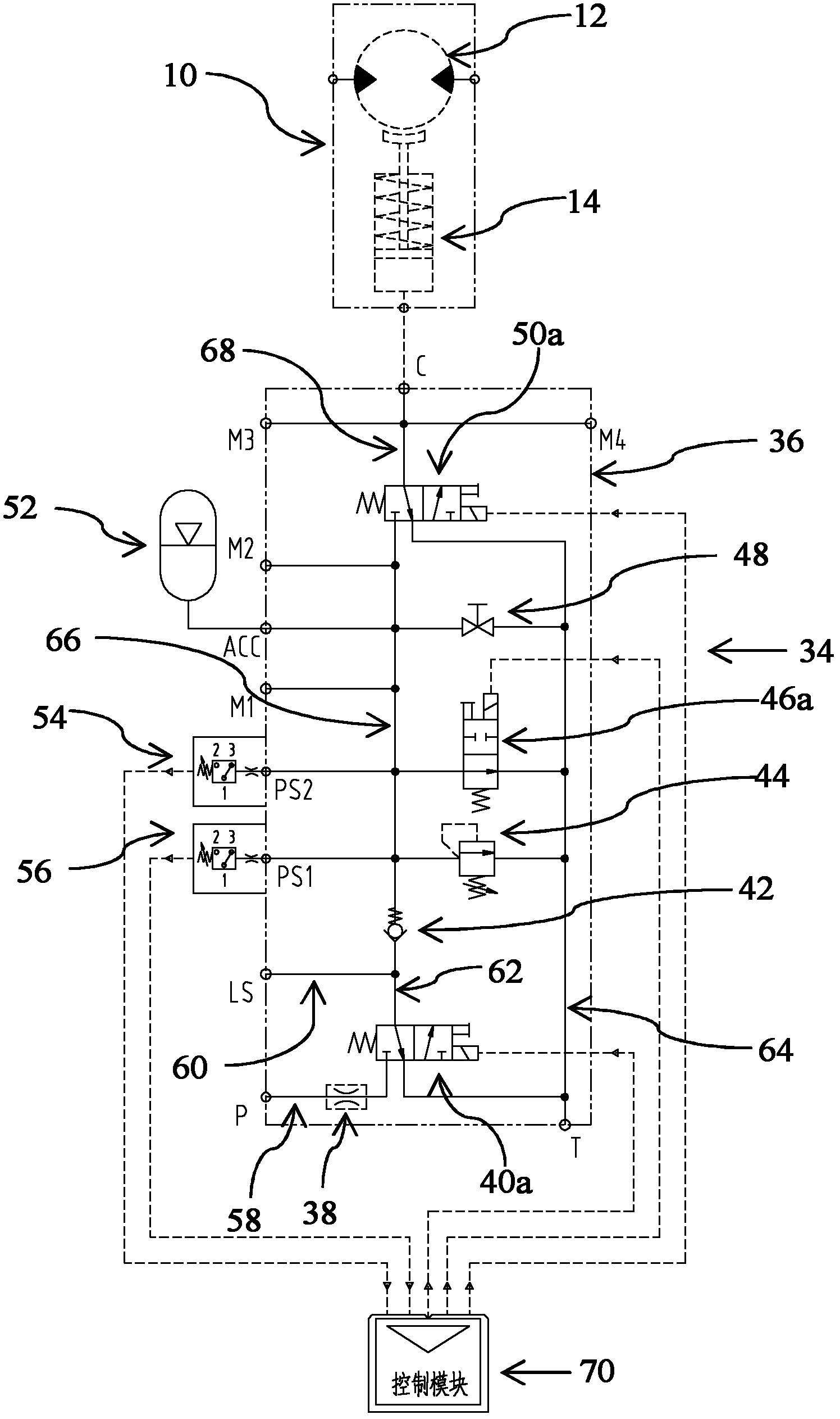
[0084] The embodiments of the present invention will be described in detail below with reference to the accompanying drawings, but the present invention can be implemented in many different ways defined and covered by the claims.

[0085] image 3 It is the hydraulic principle diagram of the first embodiment of the brake valve group of the present invention. Such as image 3 As shown, the brake valve group 34 of this embodiment includes: an accumulator 52, a pressure limiting valve 44, a first pressure switch 54 and a second pressure switch 56, an electromagnetic reversing valve 40a, a one-way valve 42, an electromagnetic reversing valve Valve 50a, ball valve 48, solenoid directional valve 46a, orifice 38, valve block 36, and control module 70.

[0086] Notice, image 3 The middle slewing reducer 10 and the hydraulic motor 12 and brake 14 in it do not belong to the brake valve group 34, and are shown here to illustrate the working principle of the brake valve group 34. Fi...


PUM


Abstract

The invention discloses a braking valve bank, which comprises an energy accumulator, a pressure detector, a liquid charging valve, a one-way valve and a working valve, wherein the energy accumulator is used for storing oil; the pressure detector is used for detecting the pressure of the oil in the energy accumulator; the liquid charging valve is arranged on a liquid charging oil path of the energy accumulator, and is used for charging liquid into the energy accumulator; the one-way valve is used for locking the oil in the liquid charging oil path and preventing the oil from reflowing; the working valve is arranged on a working oil path of the energy accumulator, and is used for controlling the oil of the energy accumulator to be released; and two independent oil paths, i.e.,, the charging oil path of the energy accumulator and the working oil path of a brake. The invention further discloses a hydraulic system having the braking valve bank and a typical operation machine, i.e., a tower type concrete spreader having the hydraulic system. The braking valve bank can be applied to braking, clamping, pressure keeping, and the like.

Description

technical field [0001] The invention relates to a brake valve group, and also relates to a hydraulic system and concrete distributing equipment with the brake valve group. Background technique [0002] At present, the booms of concrete pump trucks and placing machines are slewing through hydraulic slewing reducers and slewing supports. The hydraulic slewing reducer is driven by a hydraulic motor. The hydraulic slewing reducer has its own brake. According to whether the brake is in the braking state when stopping, the brake can be divided into two types, namely normally open and normally closed. [0003] Normally open brakes work on the principle of spring release and hydraulically applied braking. When the machine is not working, relying on the spring force, the brake is released, and the boom can rotate freely under the action of external force disturbance, such as wind load. If the brake brakes, the hydraulic system needs to provide pressure oil to enter the brake to o...

Claims


Application Information

Patent Timeline
Patent Type & Authority Applications(China)
IPC IPC(8): F15B13/02F15B1/02F15B11/02E04G21/04
Inventor 丁雪峰郭岗郭嘉博
Owner ZOOMLION HEAVY IND CO LTD
Why Eureka
Try Eureka