Energy-saving multifunctional clamping pipe control valve

A multi-functional and energy-saving technology, applied in valve details, diaphragm valves, valve devices, etc., can solve the problems of large lifting force, blockage or stuck, affecting the normal operation of the equipment, etc. of the direct lift solenoid valve, and reduce manual cleaning. frequency, impact prevention, power reduction effect

Inactive Publication Date: 2012-04-25
BEIJING LIBOMING TECH DEV
View PDF13 Cites 0 Cited by
  • Summary
  • Abstract
  • Description
  • Claims
  • Application Information

AI Technical Summary

Problems solved by technology

[0002] When the existing sprinkler dust removal system equipment is installed and used, the following defects usually occur: 1) The valve controlling the opening of the spray gun in the sprinkler dust removal system equipment is often blocked or stuck by impurities in the water (such as stones or coals, etc.) , which affects the normal operation of the equipment; 2) The direct-lift solenoid valve commonly used in the existing spray dust removal system equipment has a large lifting force and a large electromagnetic coil power (usually between 20 and 30W), resulting in large heat generation and long-term maintenance. Time work is easy to burn; 3) Moreover, the pressure change in the valve water channel will cause the spray gun to shake; 4) The opening and closing speed of the same group of valves is inconsistent, causing trouble to the control system

Method used


Image

  • Energy-saving multifunctional clamping pipe control valve
  • Energy-saving multifunctional clamping pipe control valve
  • Energy-saving multifunctional clamping pipe control valve

Examples


Embodiment Construction

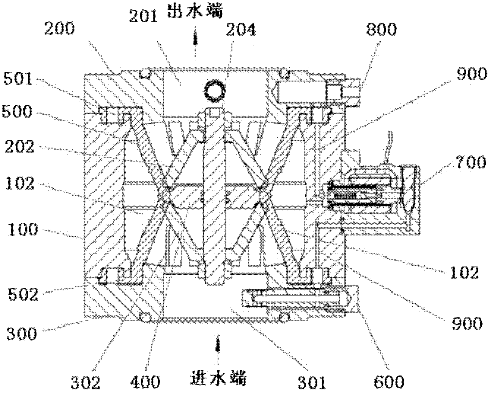
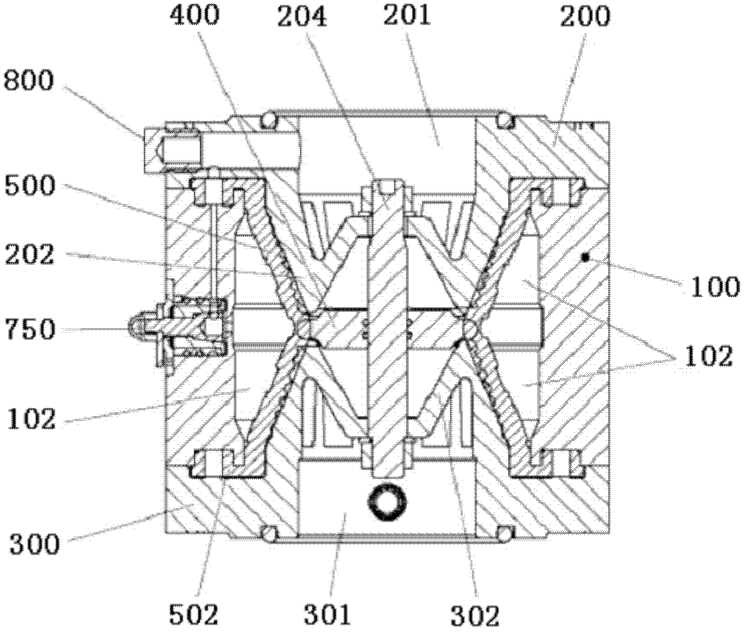
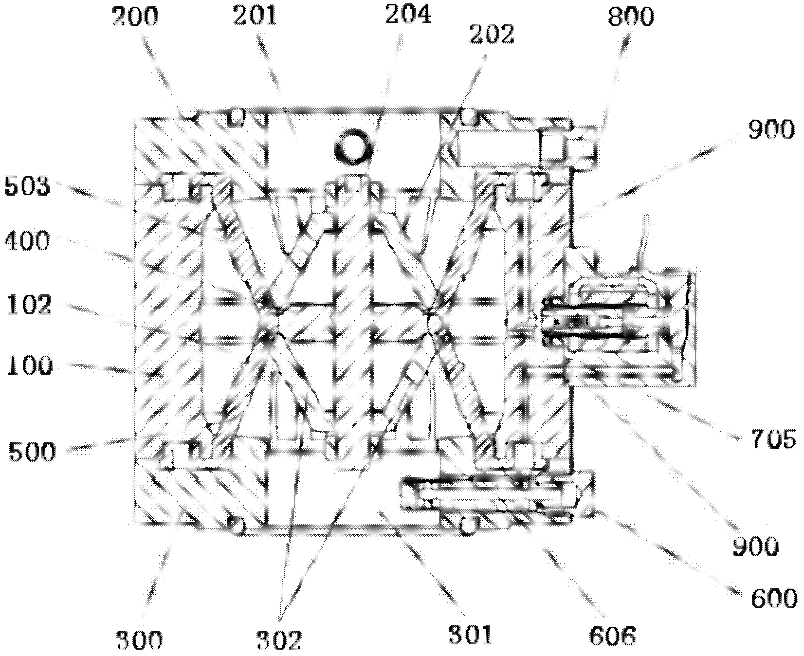
[0034] see figure 1 , 2 , 3, and 4, an energy-saving multifunctional pinch control valve of the present invention includes a valve body 100, an upper end cover 200, a lower end cover 300, an intermediate ring 400, an elastic clamp tube 500, a filter assembly 600, and an electromagnetic coil 700 And quick connector 800;

[0035] see Figure 5 , 6 , 7, the valve body 100 is provided with a hollow cylindrical through hole 101, the upper end of the valve body 100 is affixed to the upper end cover 200, and the lower end of the valve body 100 is affixed to the lower end cover 300;

[0036] see figure 1 , 2 , 3, and 4, the elastic clamp tube 500 is arranged in the through hole 101 of the valve body 100, and the upper and lower ends of the elastic clamp tube 500 are provided with fixed wings 501, 502, and the valve body 100 and the upper end cover 200 The contact part is matched with a housing cavity 102, and the fixed wing 501 at the upper end of the elastic clip tube 500 is en...


PUM


Abstract

The invention discloses an energy-saving multifunctional clamping pipe control valve, which comprises a valve body, an upper end cover with a through hole, a lower end cover with a through hole, a middle ring, an elastic clamping pipe, a filter assembly, an electromagnetic coil and a quick joint; the upper end of the valve body is fixedly connected with the upper end cover, and the lower end of the valve body is fixedly connected with the lower end cover; the elastic clamping pipe is arranged in the cavity of the valve body; a buffering cavity is formed between the outer side of the elastic clamping pipe and the valve body; the upper end cover is provided with a fixed seat protruding into the inner cavity of the valve body; the middle ring is sleeved on the middle part of a bolt; and the filter assembly passes through the side wall of a lower valve cover, the electromagnetic coil assembly is arranged on the side wall of the valve body, and the quick joint passes through the side wall of an upper valve cover. The control valve is suitable for impurity-containing water or weak corrosive liquid; the power of the electromagnetic coil is only about 10W, so the velocity of opening and closing the valve can be automatically adjusted, the pressure is automatically stabilized, and the filter is automatically flushed; and when the electromagnetic coil cannot work, the control valve has manual opening and closing function.

Description

technical field [0001] The invention relates to a valve used for spraying equipment, in particular to an energy-saving multifunctional pinch control valve. Background technique [0002] When the existing sprinkler dust removal system equipment is installed and used, the following defects usually occur: 1) The valve controlling the opening of the spray gun in the sprinkler dust removal system equipment is often blocked or stuck due to impurities in the water (such as stones or coals, etc.) , which affects the normal operation of the equipment; 2) The direct-lift solenoid valve commonly used in the existing spray dust removal system equipment has a large lifting force and a large electromagnetic coil power (usually between 20 and 30W), resulting in large heat generation and long-term maintenance. Time work is easy to burn; 3) moreover, because the change of pressure in the valve waterway can cause spray gun to shake; Therefore, it is the purpose of the present invention to pr...

Claims


Application Information

Patent Timeline
Patent Type & Authority Applications(China)
IPC IPC(8): F16K7/02F16K27/00F16K31/06F16K31/60B01D47/06
Inventor 李宝明
Owner BEIJING LIBOMING TECH DEV
Why Eureka
Try Eureka