Brushless generator in automatic voltage regulation state

An automatic voltage and generator technology, applied to synchronous generators, control of generators through magnetic field changes, magnetic circuit shape/style/structure, etc. The effect of short time required for voltage stabilization, simple structure and high reliability

Active Publication Date: 2012-04-25
浙江幸福航天科技有限公司
View PDF2 Cites 5 Cited by
  • Summary
  • Abstract
  • Description
  • Claims
  • Application Information

AI Technical Summary

Problems solved by technology

Its circuit is complicated, it takes a long time for voltage stabilization, and all the excitation current flows through the power module, which makes the power device have large capacity, lower reliability and higher cost
[0003] A kind of permanent magnet generator utilizes the constant magnetism of permanent magnets to generate electricity. Although the AVR module is not used, the change in the size and nature of the load and the change...

Method used


Image

  • Brushless generator in automatic voltage regulation state
  • Brushless generator in automatic voltage regulation state
  • Brushless generator in automatic voltage regulation state

Examples


Embodiment Construction

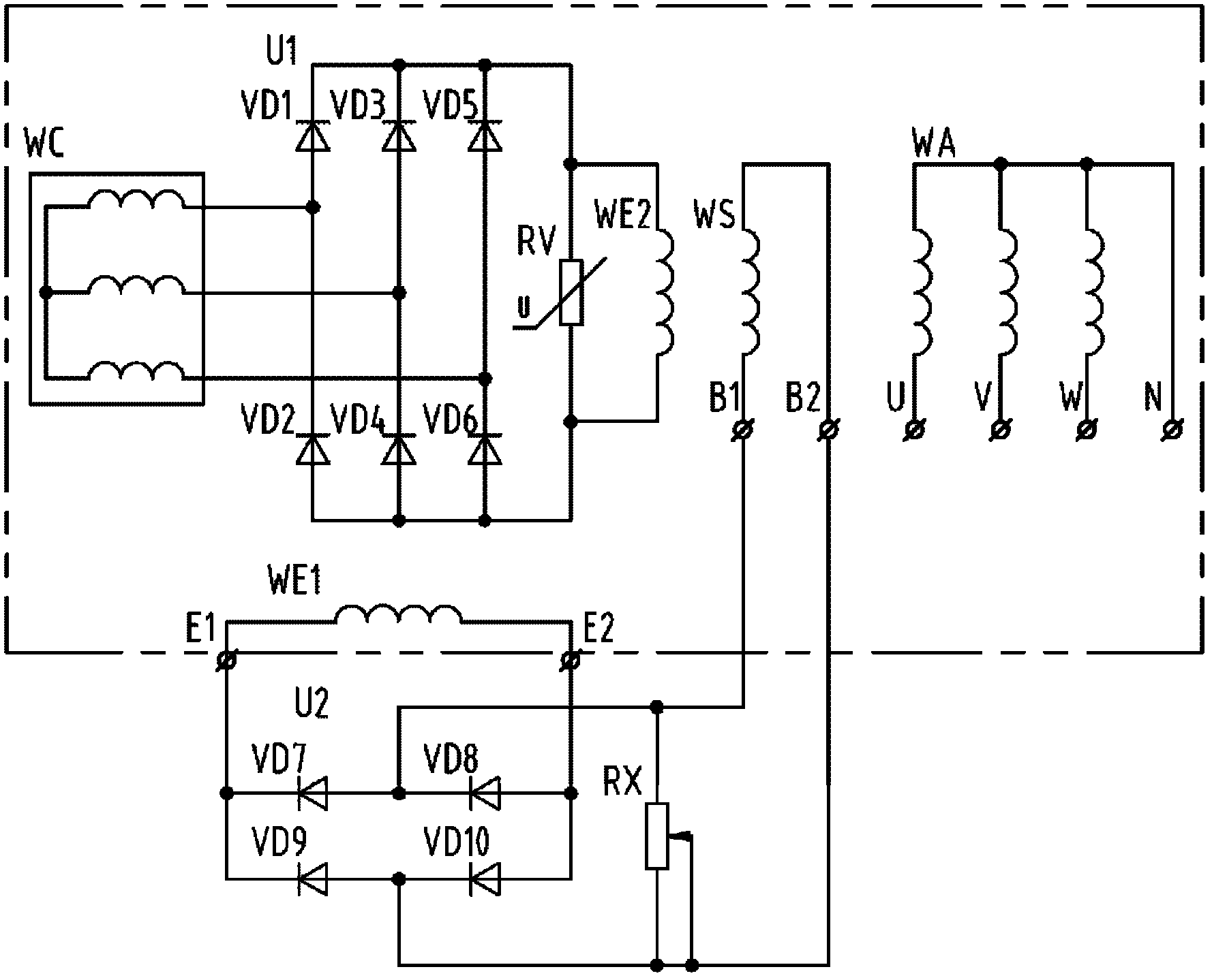
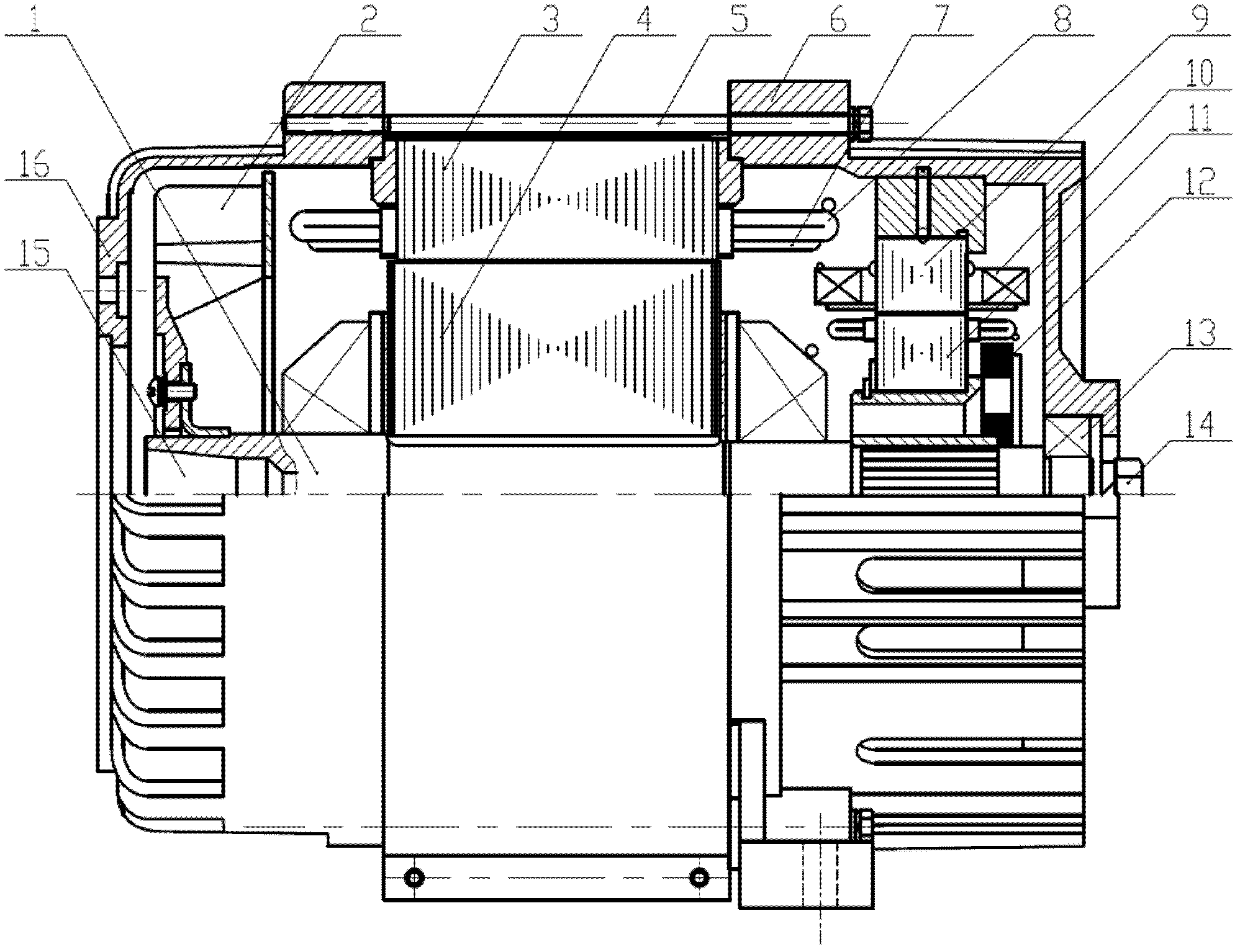
[0021] The present invention is illustrated by taking a 6GF brushless generator (6kW) as an example. Such as figure 1 Schematic diagram of the 6GF brushless generator system circuit for state automatic voltage regulation. In the figure, the 6GF generator circuit is inside the dotted line. The generator circuit includes the generator main winding WA and the exciter excitation winding WE1 in the prior art, and also includes the harmonic winding WS and the one-way rectifier bridge used in the present invention. U2, shunt resistor RX; the harmonic winding WS and the main winding WA are embedded in the generator stator 3 ( image 3 ), the two terminals B1 and B2 of the harmonic winding WS are connected to the terminals E1 and E2 of the excitation winding WE1 of the exciter through the shunt resistor RX and the one-way rectifier bridge U2. The excitation winding WE1 of the exciter is installed on the stator of the exciter. ( image 3 Among them, item 10 is the excitation winding...


PUM


Abstract

The invention relates to a brushless generator in automatic voltage regulation state. The brushless generator comprises a generator principal winding (WA) embedded in a stator (3) and is characterized by also comprising a harmonic winding (WS) embedded in the stator (3), wherein harmonic energy is taken out from the harmonic winding (WS), is rectified by an external circuit, and is sent to an exciter exciting winding (WE1); and when the states of the generator are changed, the harmonic energy is used for regulating excitation so as to stabilize the voltage of the generator. The electrode distance (tau1) of a coil (V2) of the principal winding (WA) corresponds to three electrode distances of coils (V1) of the harmonic winding (WS). A connection method for the three coils (V1) of the harmonic winding comprises the following steps of: forming a serial circuit by connecting the tail end of the coil (1) with the tail end of the coil (2), and connecting the head end of the coil (2) with the head end of the coil (3). The brushless generator can automatically regulate the voltage for stably generating power in various states, a conventional automatic voltage regulator (AVR) module is omitted, circuits of measurement devices, amplification devices, comparison devices and power controllers are saved, and the brushless generator has a simple structure, shorter required time for stabilizing voltage, high reliability and low cost.

Description

technical field [0001] The invention is a brushless generator with state automatic voltage regulation, which belongs to the technical field of generators. Background technique [0002] Existing electrically excited generators (including AC, DC, brushless, and brushed generators) all adopt differential regulation and are equipped with an automatic voltage regulation AVR module (hereinafter referred to as AVR module) in order to realize voltage stabilization. Use the AVR module to measure the voltage of the generator, and process the signal, compare, amplify, and shift the phase, and use PWM technology to control the output of the power module to adjust the excitation of the generator to achieve voltage stabilization. Its circuit is complicated, it takes a long time to stabilize the voltage, and all the excitation current flows through the power module, which makes the power device have large capacity, lower reliability and higher cost. [0003] A kind of permanent magnet gen...

Claims


Application Information

Patent Timeline
IPC IPC(8): H02K19/38H02K3/28H02K1/16H02P9/38
Inventor 王建平陈江龙
Owner 浙江幸福航天科技有限公司
Why Eureka
Try Eureka