Traversing device

A technology of reciprocating device and reciprocating motion, used in electromechanical devices, cooling/ventilation devices, transportation and packaging, etc., can solve the problems of complex structure, the possibility of torque increase, and the inability to provide structural space.

Inactive Publication Date: 2012-04-25
OERLIKON TEXTILE GMBH & CO KG
View PDF13 Cites 8 Cited by
  • Summary
  • Abstract
  • Description
  • Claims
  • Application Information

AI Technical Summary

Problems solved by technology

[0009] In the latter configuration, the possibility of increasing the torque is limited, while the reciprocating mechanism of the first type requires additional installation space at the end point of the reciprocating stroke or is very complicated in construction
However, if several yarn reels need to be arranged coaxially one behind the other, as is often the case in textile machines in the form of winding zones, this additional installation space cannot be provided.

Method used


Image

  • Traversing device
  • Traversing device
  • Traversing device

Examples


Embodiment Construction

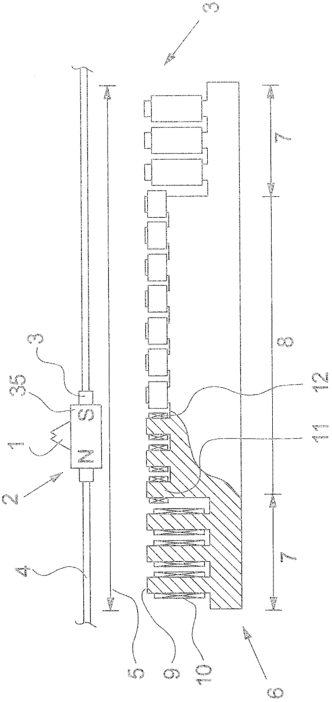
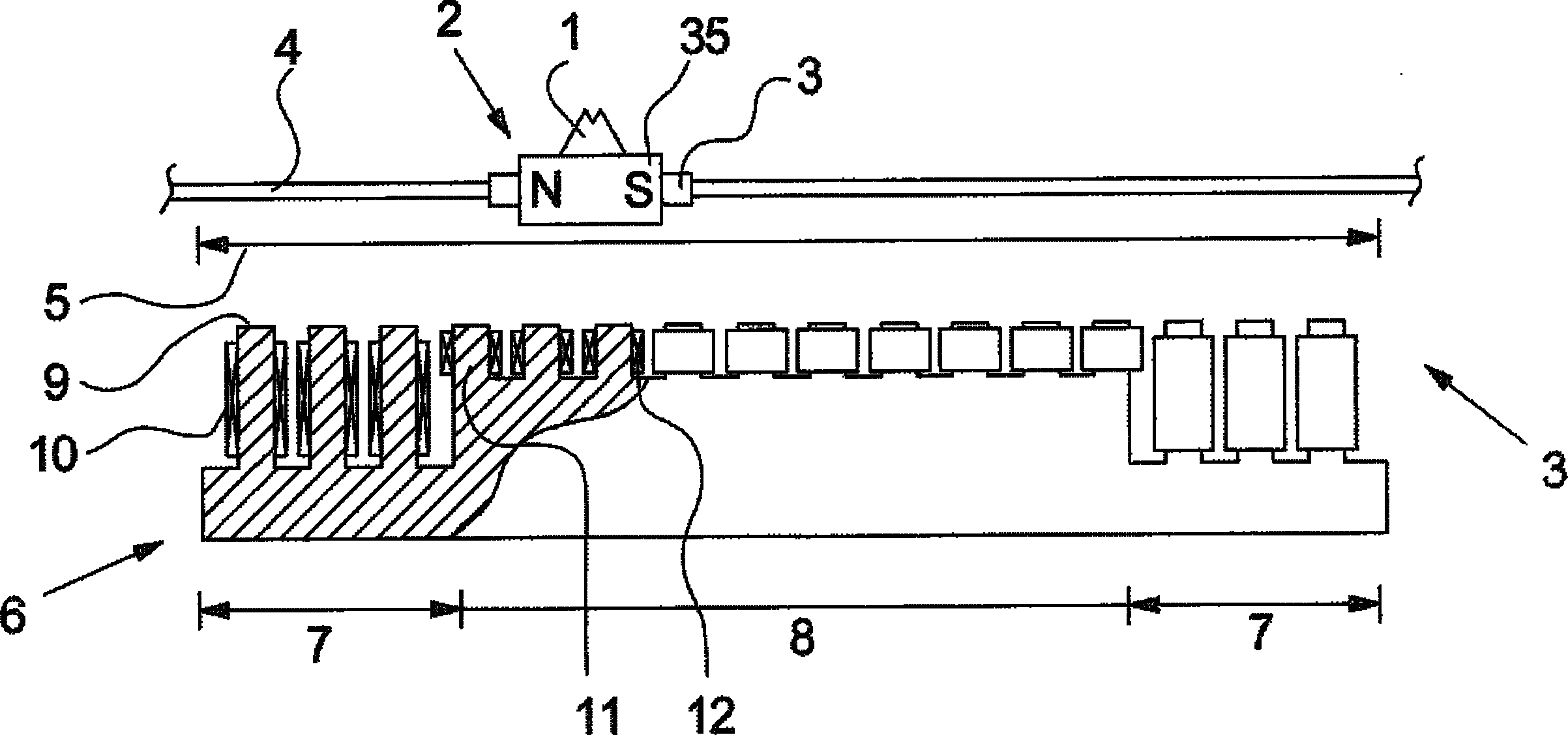
[0028] exist figure 1 shows a reciprocating device according to the invention with a drive implemented by a linear motor. The mover 2 , which is designed as a permanent magnet 35 , is guided on the guide 4 via the sleeve 3 , so that it can be guided back and forth within the reciprocating region 5 . The mover 2 carries a reciprocating yarn guide 1 for guiding the yarn to and fro by the mover 2 inside the reciprocating area 5 when winding the yarn bobbin.

[0029] The mover 2 interacts with a stator 6 which is equipped with a plurality of yokes 9 , 11 and coils 10 , 12 . The coils 10 , 11 are connected to a controllable alternating current source, so that a magnetic field is created that migrates in the longitudinal direction of the stator 6 , said magnetic field pushing the mover 2 . Here the AC power is controlled such that the direction of motion is reversed at each end of the reciprocating zone.

[0030] The region in which the direction of movement is reversed is referr...


PUM


Abstract

The invention relates to a traversing device for traversing a thread. The traversing device is driven by an electric drive (3, 13). In order to achieve a higher acceleration during reversal, a stator (6, 20) or a rotor (2, 19) of the electric drive has regions in which the electromagnetic coils (10, 12, 25, 26) or permanent magnets (30, 31) are designed to be stronger. Said regions are arranged such that they interact with each other during the reversal of the traversing thread guide. The electric drive thus is supplied with a torque or force which can be varried by way of the rotation angle or stroke, wherein the maxima of the torque or the force coincide with the reversal points of the traversing thread guide.

Description

technical field [0001] The invention relates to a reciprocating device according to the preamble of claim 1 . [0002] A reciprocating device of the described type is used to guide the continuously fed yarn back and forth parallel to the axis of the rotating sleeve so that the yarn is wound on the sleeve to form a package. Background technique [0003] Especially for cylindrical or biconical cross-wound bobbins without support discs at the ends of the bobbins, reciprocating devices are necessary which guide the yarn at a uniform speed between the reversing points and between the reversing points. Reversal points reverse the motion with very high acceleration. [0004] Various solutions are known from the prior art which satisfy the above-mentioned requirements. Due to its high flexibility in terms of reciprocating speed and the position of the reversing point, a solution in which the reciprocating yarn guide is combined with the Highly dynamic drives are connected. This ...

Claims


Application Information

Patent Timeline
Patent Type & Authority Applications(China)
IPC IPC(8): B65H54/28B65H54/38H02K7/14H02K33/16H02K41/03
CPCB65H54/2833H02K1/2733B65H2701/31H02K7/14H02K1/276B65H54/386H02K41/031H02K33/16H02K3/28H02K1/14H02K9/20H02K9/225
Inventor M·赫茨贝格S·P·辛格
Owner OERLIKON TEXTILE GMBH & CO KG
Why Eureka
Try Eureka