
Centrifugal aluminium casting method of cage type rotor of motor

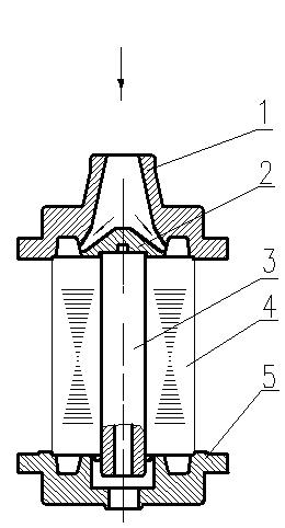
A cage-type rotor and centrifugal casting technology, which is applied in the manufacture of stator/rotor body, etc., can solve the problems of notch dissatisfaction, loose casting structure, increased motor loss, etc., and achieve the effect of avoiding air holes

Inactive Publication Date: 2012-05-02
XIANGTAN ELECTRIC MFG CORP LTD
View PDF5 Cites 10 Cited by
  • Summary
  • Abstract
  • Description
  • Claims
  • Application Information

AI Technical Summary

Problems solved by technology

[0003] (1) If the speed of the centrifuge is too high, a large centrifugal force will be generated. Under the hindrance of the large centrifugal force, it is difficult for the aluminum liquid to be smoothly injected into the lower end ring cavity through the guide groove. At the same time, the aluminum liquid is not completely filled. When the lower end ring cavity is formed, the upper aluminum liquid has begun to rapidly change from liquid shrinkage to solidification shrinkage, and the lower end ring is the last part of the aluminum liquid solidification in the cavity. When this part solidifies and shrinks, it is no longer possible to replenish the aluminum liquid. At this time, the cavity of the lower end ring can neither be filled with molten aluminum, nor can the gas in the cavity be effectively discharged, so pores or shrinkage cavities are generated;
[0004] (2) If the speed of the centrifuge is too low, the centrifugal force will be insufficient, the structure of the casting will be loose, and the aluminum liquid will not be able to fill the cavity of the guide bar or cause the notch to be dissatisfied
[0005] Therefore, the loose structure of castings and defects such as pores or shrinkage cavities will lead to increased motor loss, reduced efficiency, and even shutdown accidents, resulting in immeasurable economic losses

Method used


Image

  • Centrifugal aluminium casting method of cage type rotor of motor
  • Centrifugal aluminium casting method of cage type rotor of motor

Examples


Embodiment 1

[0024] Embodiment 1, it comprises the following steps:

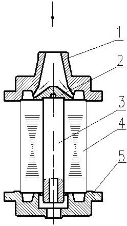
[0025] Step 1: Preheat the rotor core 4

[0026] Put the rotor core 4 into the heating furnace to preheat for 4 hours, the preheating temperature is 550°C, and keep it warm for 30 minutes after reaching the preheating temperature;

[0027] Step 2: Preheat the cast aluminum mold

[0028] Preheat the cast aluminum mold for 4 hours, and keep it warm for 15 minutes after reaching the preheating temperature. The preheating temperatures are: the preheating temperature of the cast aluminum upper mold 1 is 500°C, and the preheating temperature of the cast aluminum lower mold 5 is 200°C;

[0029] Step 3: Melting Aluminum

[0030] Smelting aluminum ingots for remelting into molten aluminum, coating cast iron crucibles and bell jars before smelting. When the temperature of the molten aluminum is 760°C±20°C, press the cylindrical composite additive into the molten aluminum to degas and modify the molten aluminum, and the reaction...

Embodiment 2

[0036] Embodiment 2, it comprises the following steps:

[0037] Put the rotor core 4 into the heating furnace to preheat for 4 hours, the preheating temperature is 530°C, and keep it warm for 30 minutes after reaching the preheating temperature;

[0038] Step 2: Preheat the cast aluminum mold

[0039] Preheat the cast aluminum mold for 4 hours, and keep it warm for 15 minutes after reaching the preheating temperature. The preheating temperatures are: the preheating temperature of the cast aluminum upper mold 1 is 500°C, and the preheating temperature of the cast aluminum lower mold 5 is 200°C;

[0040] Step 3: Melting Aluminum

[0041] Smelting aluminum ingots for remelting into molten aluminum, coating cast iron crucibles and bell jars before smelting. When the temperature of the molten aluminum is 760°C±20°C, press the cylindrical composite additive into the molten aluminum to degas and modify the molten aluminum, and the reaction duration is 10±5 minutes. Add 0.5-1kg of ...

Embodiment 3

[0047] Embodiment 3, it comprises the following steps:

[0048] Put the rotor core 4 into the heating furnace to preheat for 4 hours, the preheating temperature is 500°C, and keep it warm for 25 minutes after reaching the preheating temperature;

[0049] Step 2: Preheat the cast aluminum mold

[0050] Preheat the cast aluminum mold for 4 hours, and keep it warm for 15 minutes after reaching the preheating temperature. The preheating temperatures are: the preheating temperature of the cast aluminum upper mold 1 is 500°C, and the preheating temperature of the cast aluminum lower mold 5 is 200°C;

[0051] Step 3: Melting Aluminum

[0052] Smelting aluminum ingots for remelting into molten aluminum, coating cast iron crucibles and bell jars before smelting. When the temperature of the molten aluminum is 760°C±20°C, press the cylindrical composite additive into the molten aluminum to degas and modify the molten aluminum, and the reaction duration is 10±5 minutes. Add 0.5-1kg of ...


PUM


Abstract

The invention provides a centrifugal aluminum casting method of a cage type rotor of a motor. The centrifugal aluminum casting method comprises the following steps of: 1, preheating a rotor iron core; 2, preheating an aluminum casting die; 3, melting aluminum; 4, centrifugally casting: clamping the rotor iron core and the aluminum casting die which reach preheating requirement onto a centrifugal machine, starting the centrifugal machine to stably rotate according to a set initial rotating speed, rapidly injecting aluminum liquid from an upper die sprue of the aluminum casting die at the time, starting a centrifugal machine accelerating button when a die cavity is filled with the aluminum liquid, so that the centrifugal machine rotates according to the set full speed; and 5, dismantling the die after the centrifugal machine naturally stops and the aluminum liquid is solidified. The centrifugal aluminum casting method disclosed by the invention gives different centrifugal machine rotating speeds according to rotors of different diameter sections and effectively avoids castings from generating object quality defects, such as air pores, shrinkage cavities, tissue loosening and the like.

Description

technical field [0001] The invention relates to the field of manufacturing medium-sized motors, and relates to a method for centrifugally casting aluminum on a cage-type rotor of a motor. Background technique [0002] For domestically manufactured medium-sized motor cage rotors, when adopting the process of centrifugal casting aluminum, it is necessary to test and explore to determine the centrifuge speed, and it is difficult to grasp the correct and reasonable centrifuge speed after repeated tests, or the speed is too high, or It's low speed. The theoretically calculated value of the centrifuge speed is about 350-600 r / min. [0003] (1) If the speed of the centrifuge is too high, a large centrifugal force will be generated. Under the hindrance of the large centrifugal force, it is difficult for the aluminum liquid to be smoothly injected into the lower end ring cavity through the guide groove. At the same time, the aluminum liquid is not completely filled. When the lower ...

Claims


Application Information

Patent Timeline
Patent Type & Authority Applications(China)
IPC IPC(8): B22D13/00H02K15/02
Inventor 刘铁唐朝阳付彩明
Owner XIANGTAN ELECTRIC MFG CORP LTD
Learn More