Device for machining pipe fitting by using lathe

A technology for lathe processing and pipe fittings, applied in boring/drilling devices, metal processing equipment, manufacturing tools, etc., can solve the problems of complicated clamping and high cost, and achieve the effects of reliable clamping, high production efficiency and simple structure

Inactive Publication Date: 2012-05-02
XIAN AEROSPACEMOTOR MACHINE FACTORY
View PDF11 Cites 5 Cited by
  • Summary
  • Abstract
  • Description
  • Claims
  • Application Information

AI Technical Summary

Problems solved by technology

[0004] In order to overcome the disadvantages of complex clamping and high cost of boring machine processing in the prior art, the present invention proposes a device for processing pipe fittings using a lathe

Method used


Image

  • Device for machining pipe fitting by using lathe
  • Device for machining pipe fitting by using lathe
  • Device for machining pipe fitting by using lathe

Examples


Embodiment Construction

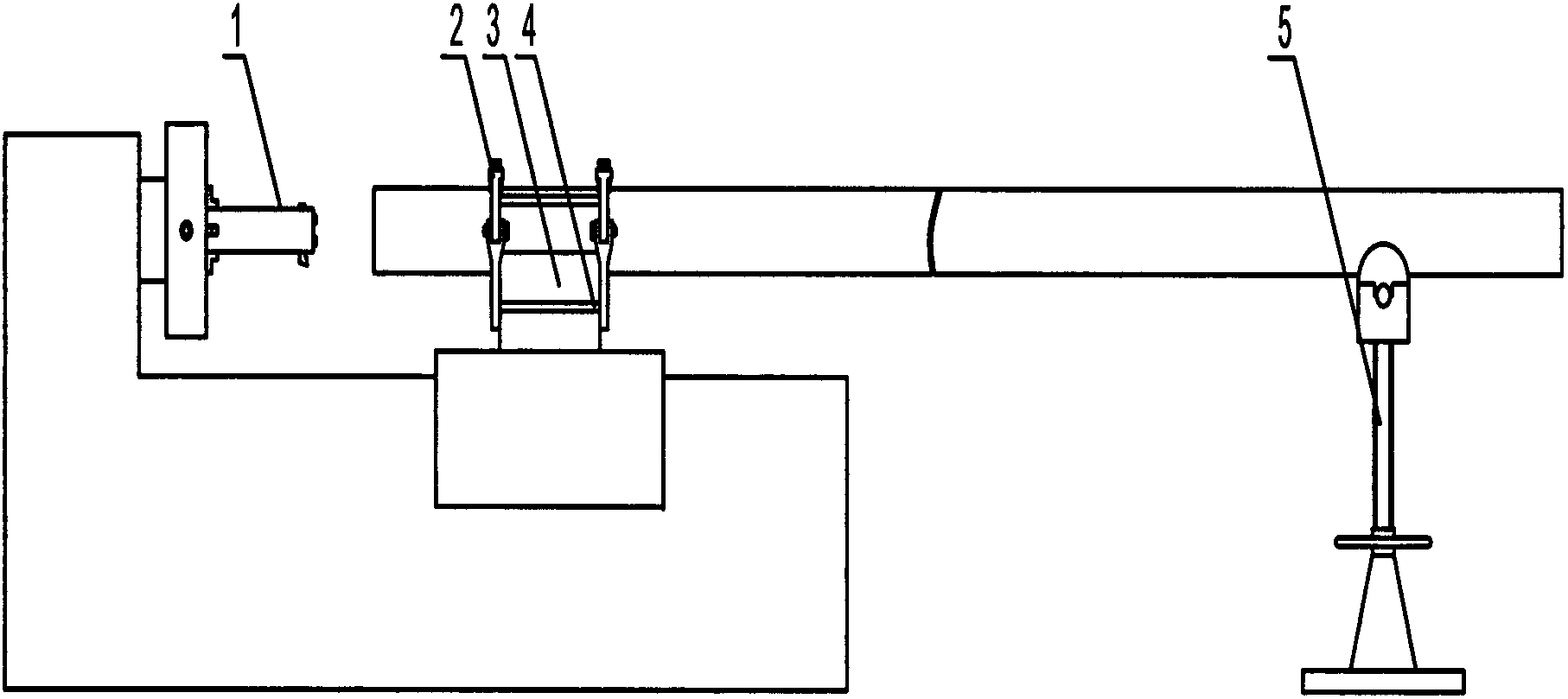
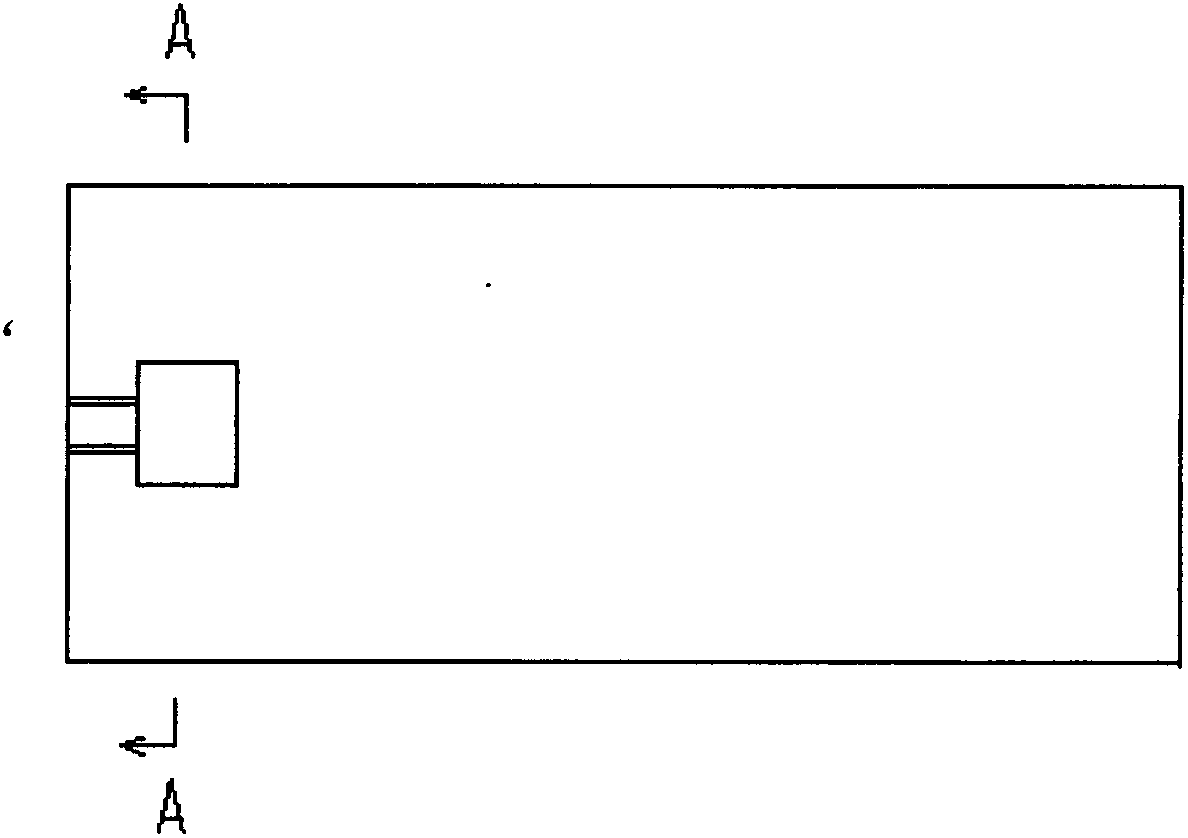
[0022] This embodiment is a device for processing pipe fittings using a C-630 lathe.

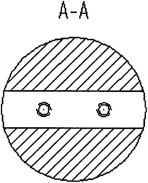
[0023] as attached figure 1 , This embodiment includes a tool holder 1, a clamp 2, a positioning block 3, a transition connecting plate 4, and a screw support frame 5. Wherein, one end of the tool rest 1 is clamped on the chuck of the main shaft of the lathe. The clamp 2 is fixed on the transition connection plate 4 through the connection plate located on the lower clamping body 7 . The transition connecting plate 4 is fixedly connected with the carriage in the lathe. The clamp 2 includes an upper clamping body 6 and a lower clamping body 7, the upper clamping body 6 is inserted into the splint at the two ends of the lower clamping body 7, and is connected by a shaft pin 10; the pressing pad 9 passes through Clamping bolts 8 are fixed on the inner surface of the upper clamping body 6 .

[0024] The tool holder 1 is a cylinder, and it is made of 45# steel bar stock quenched and tempered i...


PUM

PropertyMeasurementUnit
sizeaaaaaaaaaa

Abstract

The invention relates to a device for machining a pipe fitting by using a lathe. The device comprises a knife rest, a clamp unit, a V-shaped locating block, a transition connecting plate and a compression cushion block, wherein one end of the knife rest is clamped on a chuck of a lathe spindle, a knife mounting hole is arranged on the circumference at one end of the knife reset, and a knife fixing hole mutually perpendicular to the knife mounting hole is formed on the end face of the end of the knife rest; the clamp unit is fixed on the transition connecting plate through a connecting plate on a lower clamp body; the transition connecting plate is fixedly connected with a drag plate in the lathe; the clamp unit comprises an upper clamp body and the lower clamp body, the upper clamp body is inserted into clamp plates at both end heads of the lower clamp body and is connected with the clamp plates through shaft pins; and the compression cushion block is fixed on the inner surface of the lower clamp body through clamp bolts. According to the invention, the difficulty in machining an inner hole at the end of a bimetal composite pipe is solved, the machining efficiency is improved, and the machining cost is lowered. After the device is removed, a small drag plate, a knife rest system and a tailstock of the original lathe are installed, and the structure and the function of the original lathe can be recovered.

Description

technical field [0001] The invention relates to the mechanical processing industry, in particular to a device for processing the inner hole at the end of a bimetal composite pipe fitting on a common lathe. Background technique [0002] With the rapid development of my country's national economy, investment in the petroleum industry has increased, and bimetallic composite pipes have been increasingly widely used in the petrochemical industry due to their excellent corrosion resistance and economical price advantages. In order to ensure the quality of the joints on the long-distance (usually several kilometers or tens of kilometers or even hundreds of kilometers) bimetallic composite pipelines, in the manufacturing process of bimetallic composite pipes, the explosive composite lining is usually carried out first, Then remove the liner at the end of the pipe by machining, and after surfacing, finish machining the aperture on the surfacing layer to meet its use requirements. ...

Claims


Application Information

Patent Timeline
Patent Type & Authority Applications(China)
IPC IPC(8): B23B43/00
Inventor 何星张雨霏王维郝君伟王浩刚贺光明何锋
Owner XIAN AEROSPACEMOTOR MACHINE FACTORY
Why Eureka
Try Eureka