
Ultralow interface tension coupling type air-foam oil displacement method
An air foam flooding and interfacial tension technology, which is applied in earthwork drilling, production fluid, wellbore/well components, etc., can solve the problems of single oil displacement mechanism, low oil displacement efficiency, and low degree of crude oil production, and achieve improved displacement. Oil efficiency, increased seepage resistance, and enhanced oil recovery
- Summary
- Abstract
- Description
- Claims
- Application Information
AI Technical Summary
Problems solved by technology
Method used
Image

Examples
Embodiment 1
[0033] Example 1: Extreme water flooding double-pipe parallel core experiment
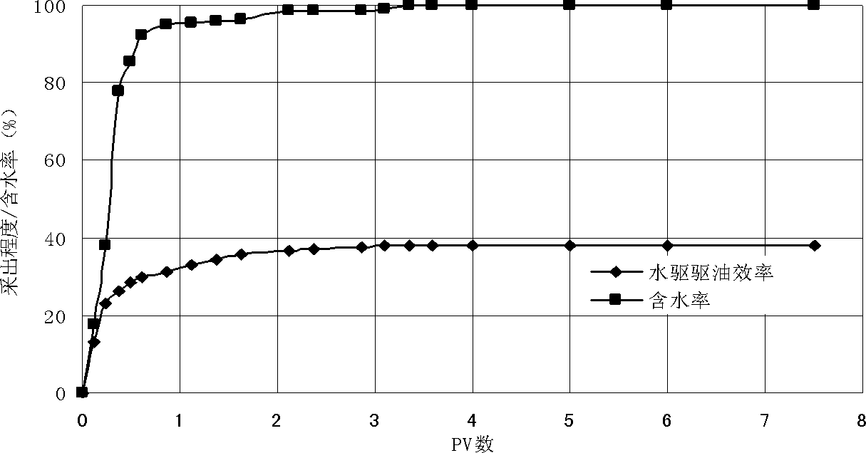
[0034] A group of double-pipe parallel cores (saturated with oil) were connected to the water flooding experiment process (the temperature has been kept at the reservoir temperature), and the water flooding experiment was carried out at a water flooding speed of 5m / d. %), continue water flooding for 5PV, and end the experiment when the outlet no longer produces oil. During the displacement process, record the pressure change value, water cut and recovery degree change at every 0.1PV interval, and calculate the ultimate recovery. For details, see attached figure 1 .
Embodiment 2
[0035] Example 2: Air flooding double-pipe parallel core experiment
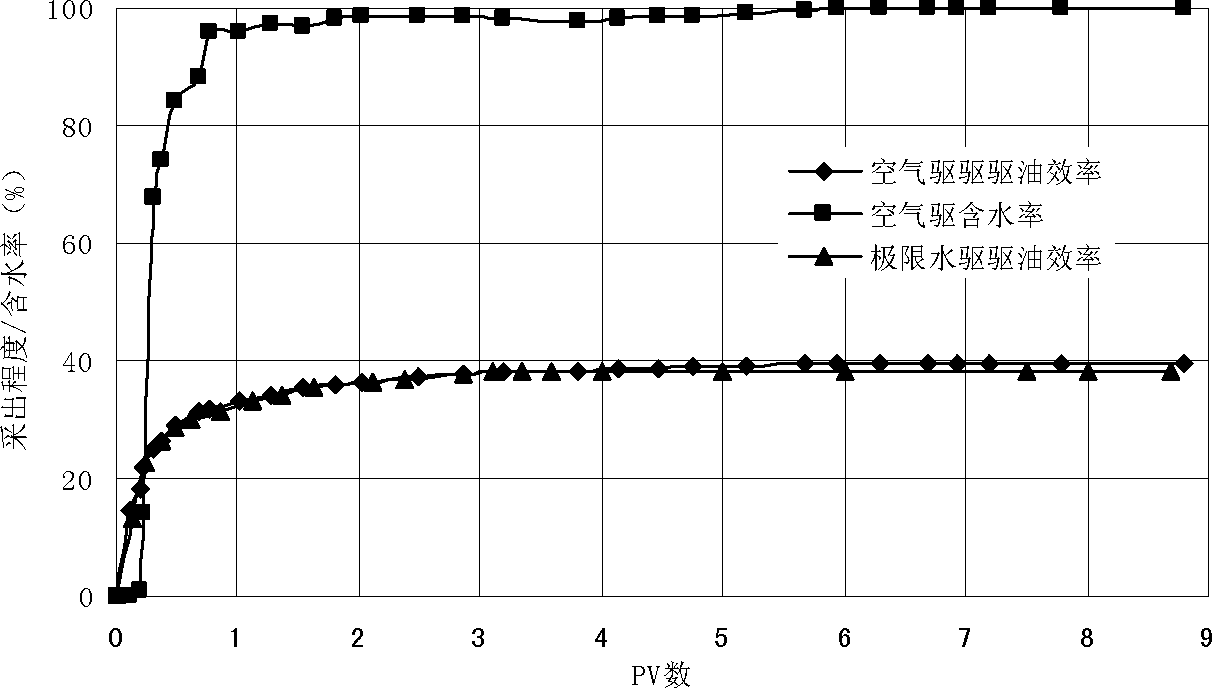
[0036] A group of double-pipe parallel cores were connected to the water flooding experimental process (the temperature has been kept at the reservoir temperature), and the water flooding was carried out at a water flooding speed of 5m / d. The air mass flowmeter controls the volume under injection pressure) 4PV, and then the subsequent water flooding 1PV to end the experiment; during the displacement process, the displacement speed of air is consistent with the displacement speed of water displacement, and the pressure change value is recorded every 0.1PV interval , water cut and recovery degree changes, and calculate the ultimate recovery rate, see the attached figure 2 .
Embodiment 3
[0037] Example 3: Pure foaming agent (surfactant) flooding double-pipe parallel core experiment
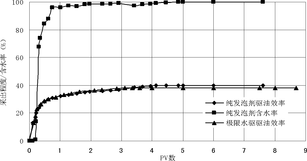
[0038]Connect a group of double-pipe parallel cores into the water flooding experimental process (the temperature has been kept at the reservoir temperature), and carry out water flooding at a water flooding speed of 5m / d. The prepared surfactant solution displaces 4PV, followed by water flooding for 1PV to end the experiment; during the displacement process, the displacement speed of air is consistent with that of water displacement, and the pressure change, water content and Changes in recovery degree, calculation of ultimate recovery, see attached image 3 .
PUM
 Abstract
Description
Claims
Application Information