Aspirating type combined pulse detonation engine with secondary detonation

A detonation engine, combined pulse technology, applied in the direction of machine/engine, rocket engine device, mechanical equipment, etc., can solve the problem that the secondary detonation cannot be maintained for a long time, the amount of ejected air is limited, and the air supply is insufficient, etc. Insufficient oxidant, long detonation working time, favorable effect for successful transformation

Inactive Publication Date: 2012-05-02
NORTHWESTERN POLYTECHNICAL UNIV
View PDF7 Cites 12 Cited by
  • Summary
  • Abstract
  • Description
  • Claims
  • Application Information

AI Technical Summary

Problems solved by technology

Experiments have shown that detonation can be successfully achieved by using the engine disclosed in the patent, but the experiment can only be maintained for a short period of time. The main reason for this phenomenon is the insufficient supply of air (oxidant) in the main detonation chamber
A baffle is installed at the front end of the main detonation chamber to prevent backfire propagation of the mixture in the main detonation chamber due to the tempering of the main detonation chamber. However, the baffle severely restricts the amount of ejected air, causing the secondary detonation to be unable to last for a long time.

Method used


Image

  • Aspirating type combined pulse detonation engine with secondary detonation
  • Aspirating type combined pulse detonation engine with secondary detonation
  • Aspirating type combined pulse detonation engine with secondary detonation

Examples


Embodiment 1

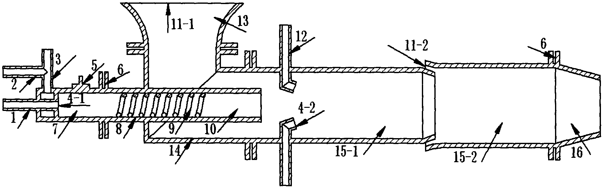
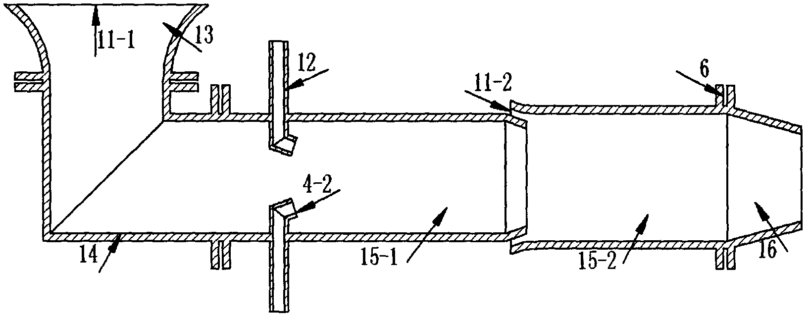
[0022] Such as figure 1 As shown, the air-breathing combined pulse detonation engine given in this embodiment includes a pre-detonation tube and a main detonation chamber.

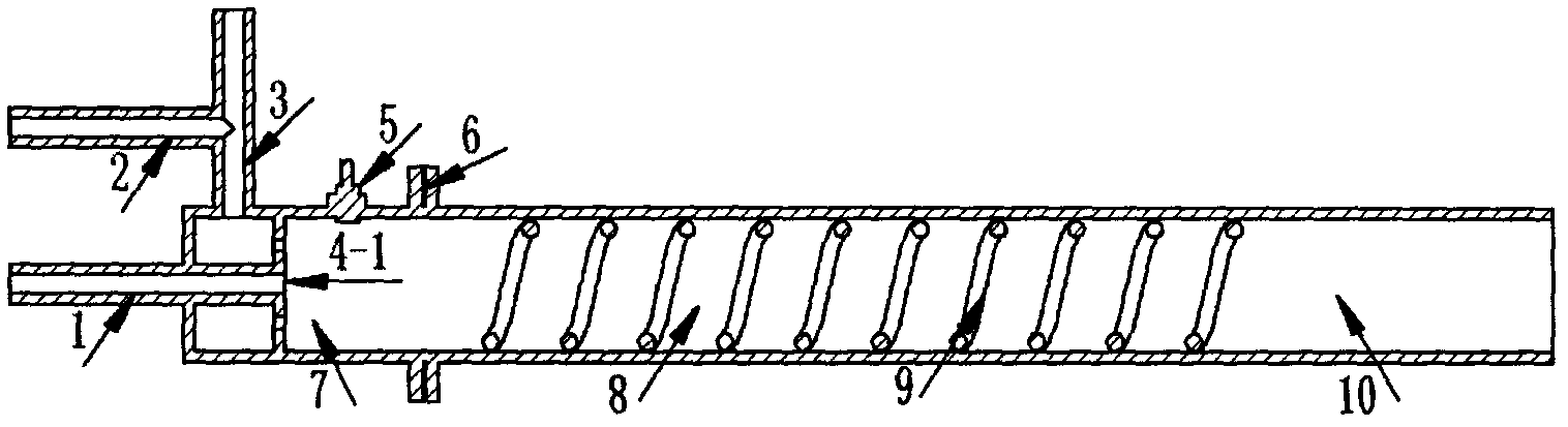
[0023] Such as figure 2 As shown, the pre-detonator includes a pre-detonator head 7 , a pre-detonator detonation forming section 8 and a pre-detonator detonation propagation section 10 . The pre-explosion tube head 7 is a round tube with one end closed and one end open. The wall of the closed end of the pre-explosion tube head 7 is provided with a fuel inlet 1, an oxidant inlet 2 and an insulating gas inlet 3. The filling of the insulating gas is to prevent Premature ignition occurs, the oxidant and isolation gas enter the pre-explosion tube head 7 through the oxidant inlet 2 and the isolation gas inlet 3, the spark plug 5 is installed on the tube wall of the pre-explosion tube head 7, and the center of the installation position of the spark plug 5 is in line with the pre-explosion tube The distance of ...

Embodiment 2

[0031]Such as figure 1 As shown, the air-breathing combined pulse detonation engine given in this embodiment includes a pre-detonation tube and a main detonation chamber.

[0032] Such as figure 2 As shown, the pre-detonator includes a pre-detonator head 7 , a pre-detonator detonation forming section 8 and a pre-detonator detonation propagation section 10 . The pre-explosion tube head 7 is a round tube with one end closed and one end open. The wall of the closed end of the pre-explosion tube head 7 is provided with a fuel inlet 1, an oxidant inlet 2 and an insulating gas inlet 3. The filling of the insulating gas is to prevent Premature ignition occurs, the oxidant and isolation gas enter the pre-explosion tube head 7 through the oxidant inlet 2 and the isolation gas inlet 3, the spark plug 5 is installed on the tube wall of the pre-explosion tube head 7, and the center of the installation position of the spark plug 5 is in line with the pre-explosion tube The distance of t...

Embodiment 3

[0040] Such as figure 1 As shown, the air-breathing combined pulse detonation engine given in this embodiment includes a pre-detonation tube and a main detonation chamber.

[0041] Such as figure 2 As shown, the pre-detonator includes a pre-detonator head 7 , a pre-detonator detonation forming section 8 and a pre-detonator detonation propagation section 10 . The pre-explosion tube head 7 is a round tube with one end closed and one end open. The wall of the closed end of the pre-explosion tube head 7 is provided with a fuel inlet 1, an oxidant inlet 2 and an insulating gas inlet 3. The filling of the insulating gas is to prevent Premature ignition occurs, the oxidant and isolation gas enter the pre-explosion tube head 7 through the oxidant inlet 2 and the isolation gas inlet 3, the spark plug 5 is installed on the tube wall of the pre-explosion tube head 7, and the center of the installation position of the spark plug 5 is in line with the pre-explosion tube The distance of ...


PUM


Abstract

The invention provides an aspirating type combined pulse detonation engine with a secondary detonation, comprising a predetonation pipe and a main detonation chamber, wherein the main detonation chamber comprises an inspiratory horn nozzle, a rotary joint, a main detonation forming chamber and a contracting nozzle; the rotary joint is a 90 degrees turned circular tube structure; the main detonation forming chamber is composed of two stages circular tubes coaxially connected; the two ends of the rotary joint are fixedly connected with the inspiratory horn nozzle and the first stage circular tube of the main detonation forming chamber; the predetonation pipe is inserted through the pipe wall on one side of the inspiratory horn nozzle, wherein the side is connected with the rotary joint. The aspirating type combined pulse detonation engine makes use of high temperature and high pressure products discharged from the predetonation pipe and can effectively inject outside fresh air into the main detonation forming chamber. The inspiratory horn nozzle is connected with the main detonation forming chamber through the rotary joint to effectively prevent tempering and reversed transmission, and increase the injected air amount. A gap is arranged between the first stage circular tube and the second stage circular tube of the main detonation forming chamber, wherein the outside air enters the main detonation forming chamber through the gap to increase the filling amount of oxidants in back end of the main detonation chamber.

Description

technical field [0001] The invention relates to the technical field of engines, in particular to an air-breathing combined pulse detonation engine with secondary detonation. Background technique [0002] The pulse detonation engine is a new concept engine that uses pulse detonation waves to generate thrust. It has the advantages of simple structure, light weight, large thrust-to-weight ratio, and low unit fuel consumption rate. Pulse detonation engines are divided into two structural forms: self-breathing type and rocket type according to the different ways of oxidant supply. Their basic principles are the same, the difference is that the air-breathing pulse detonation engine obtains the oxidant from the air, while the rocket-type pulse detonation engine needs its own oxidant. Compared with the rocket-type pulse detonation engine, the air-breathing pulse detonation engine has many advantages: it can obtain oxygen from the atmosphere without its own oxidant, which can make ...

Claims


Application Information

Patent Timeline
Patent Type & Authority Applications(China)
IPC IPC(8): F02K9/62
Inventor 范玮严宇高瞻穆杨朱旭东
Owner NORTHWESTERN POLYTECHNICAL UNIV
Why Eureka
Try Eureka