Rigid vacuum insulating plate and manufacturing method thereof

A vacuum insulation panel and rigid technology, which is applied to heat exchange equipment, protects pipelines through heat insulation, heat preservation, etc., can solve the problems of increasing the thermal conductivity of vacuum insulation panels, increasing the difficulty and cost of use, and easy aging of the thin film barrier layer. To achieve the effect of easy recycling, good compactness and low thermal conductivity

Inactive Publication Date: 2012-05-02
NANJING UNIV OF AERONAUTICS & ASTRONAUTICS
View PDF4 Cites 20 Cited by
  • Summary
  • Abstract
  • Description
  • Claims
  • Application Information

AI Technical Summary

Problems solved by technology

[0003] The material of the barrier layer of the vacuum insulation panel reported in the literature is mainly composed of plastic film and aluminum film. The vacuum insulation panel cannot withstand large external forces and is very easy to be damaged. The installation of the vacuum insulation panel often requires additional protection measure

Method used


Image

  • Rigid vacuum insulating plate and manufacturing method thereof
  • Rigid vacuum insulating plate and manufacturing method thereof
  • Rigid vacuum insulating plate and manufacturing method thereof

Examples


Embodiment 1

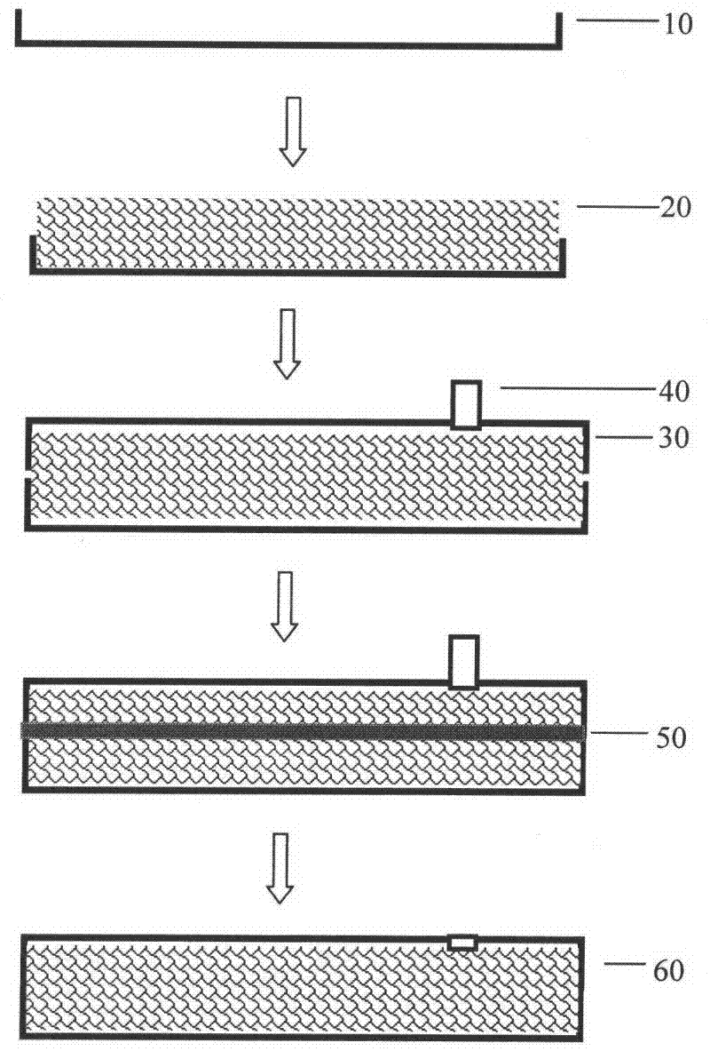
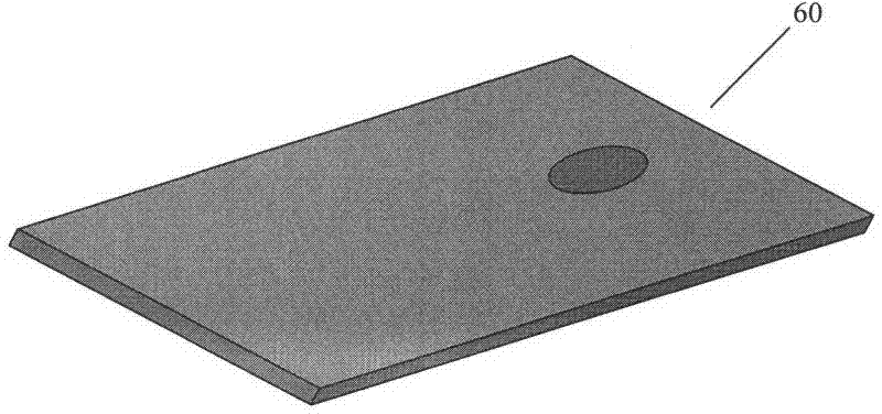
[0022] A rigid vacuum insulation panel 60. The vacuum insulation panel is assembled, welded, vacuumed and sealed by a metal barrier panel shell and an inorganic porous core material. The thermal conductivity of the vacuum insulation panel is 4mW / m·K. meters can withstand a counterweight weighing 1 ton. The rigid vacuum insulation panel 60 described in this example includes: a stainless steel metal barrier lower shell plate 10 with a thickness of 0.5 mm, a porous core material 20 of a fumed silica powder plate with a porosity of 50%, a stainless steel metal barrier plate and a shell plate 30. The specific steps of the manufacturing method of the rigid vacuum insulation panel 60 are as follows:

[0023] (1) Stamping a stainless steel flat plate into a lower shell plate 10 and an upper shell plate 30, and punching air extraction holes on the surface of the upper shell plate 30;

[0024] (2) copper air extraction pipe 40 is welded on the air extraction hole;

[0025] (3) Put th...

Embodiment 2

[0031] A rigid vacuum insulation panel 60. The vacuum insulation panel is assembled, welded, vacuumized and sealed by a metal barrier panel shell and an inorganic porous core material. The thermal conductivity of the vacuum insulation panel is 6mW / m·K, per square meter The meter can bear a counterweight of 1.2 tons. The rigid vacuum insulation panel 60 described in this example includes: a titanium alloy barrier lower shell plate 10 with a thickness of 0.7 mm, a porous core material 20 of glass wool felt with a porosity of 45%, and a titanium alloy barrier plate shell plate 30 . The specific steps of the manufacturing method of the rigid vacuum insulation panel 60 are as follows:

[0032] (1) Stamping the titanium alloy flat plate into the lower shell plate 10 and the upper shell plate 30, and punching out air extraction holes on the surface of the upper shell plate 30;

[0033] (2) copper air extraction pipe 40 is welded on the air extraction hole;

[0034] (3) Put the glas...


PUM

PropertyMeasurementUnit
Thicknessaaaaaaaaaa

Abstract

The invention discloses a rigid vacuum insulating plate, which is characterized in that the rigid vacuum insulating plate is combined by a sealed metal separating plate housing and internal inorganic porous core material; the heat conductive coefficient of the vacuum insulating plate is 3-10mW/m.K; each one square meter of the vacuum insulating plate can bear 1-2 ton of counter without being deformed and can be kept airproof when the insulating board is punctured by needles and grinded by grains of sand; the housing of the separating plate is made from stainless steel or titanium alloy with thickness of 0.2-1.2mm, but is not limited to stainless steel or titanium alloy; the inorganic porous core material is glass wool felt or gas phase silicon dioxide with porosity of 40-80%, but is not limited to glass wool felt or gas phase silicon dioxide. A manufacturing method for the rigid vacuum insulating plate is further disclosed in the invention. The vacuum insulating board provided by the invention can be directly used as insulating materials for buildings as well as insulating floors for refrigeration houses and ships.

Description

technical field [0001] The invention relates to a vacuum heat insulation material and heat insulation material engineering technology, in particular to a rigid vacuum heat insulation board and a preparation method thereof. Background technique [0002] Vacuum insulation panel is a kind of super insulation material. When it is the same thickness, its thermal conductivity is often 5 to 10 times lower than that of traditional insulation materials. It is precisely because of its excellent thermal insulation performance and limited thickness that vacuum insulation panels have become the mainstream thermal insulation materials for places with high thermal insulation requirements and limited space. [0003] The material of the barrier layer of the vacuum insulation panel reported in the literature is mainly composed of plastic film and aluminum film. The vacuum insulation panel cannot withstand large external forces and is very easy to be damaged. The installation of the vacuum ins...

Claims


Application Information

Patent Timeline
IPC IPC(8): F16L59/065
Inventor 陈照峰张卷李斌斌陈照海
Owner NANJING UNIV OF AERONAUTICS & ASTRONAUTICS
Why Eureka
Try Eureka