

RCS (radar cross section) measurement device based on single continuous terahertz laser source
A measurement device, terahertz technology, applied in the field of terahertz radar scattering cross-section measurement, to achieve high-precision measurement, reduce measurement error, and simple structure
- Summary
- Abstract
- Description
- Claims
- Application Information
AI Technical Summary
Problems solved by technology
Method used
Image

Examples
specific Embodiment approach 1
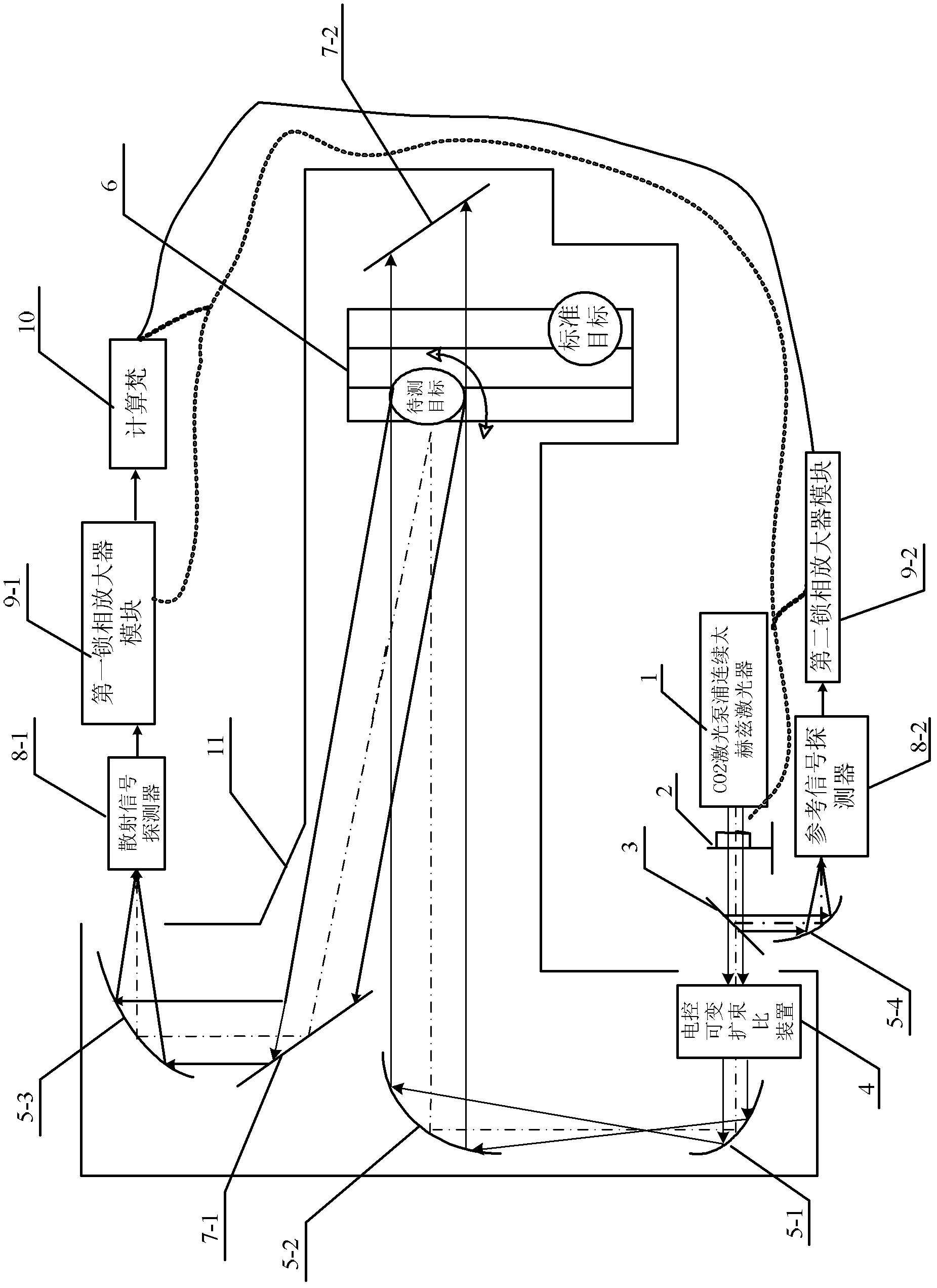
[0053] Specific implementation mode one: the following combination Figure 1 to Figure 9 Describe this embodiment, the RCS measurement device based on a single continuous terahertz laser source in this embodiment, it includes a CO2 laser pumped continuous terahertz laser 1, a chopper 2, a beam splitter 3, an electronically controlled variable beam expander Ratio device 4, P3 off-axis parabolic mirror 5-1, P2 off-axis parabolic mirror 5-2, precision motion platform 6, M1 total reflection mirror 7-1, P1 off-axis parabolic mirror 5-3, scattered signal detector 8- 1, the driver of the first lock-in amplifier module 9-1, computer 10 and chopper,
[0054] The parallel beam output by the CO2 laser pumped continuous terahertz laser 1 is chopped by the chopper 2 and then incident on the beam splitter 3, and the transmitted beam transmitted by the beam splitter 3 is expanded by the electronically controlled variable beam expansion ratio device 4 and then incident To the P3 off-axis par...
specific Embodiment approach 2
[0061] Specific implementation mode two: the following combination figure 1 Describe this embodiment, this embodiment is a further description of Embodiment 1, the measuring device also includes a P4 off-axis parabolic mirror 5-4, a reference signal detector 8-2 and a second lock-in amplifier module 9-2,
[0062] The reflected light of the beam splitter 3 is incident on the P4 off-axis parabolic mirror 5-4, and the output beam formed by the reflection of the P4 off-axis parabolic mirror 5-4 is received by the photosensitive surface of the reference signal detector 8-2, and the reference signal detector 8- The electrical signal output end of 2 connects the electrical signal input end of the second lock-in amplifier module 9-2, and the amplified signal output end of the second lock-in amplifier module 9-2 connects the reference signal input end of the data acquisition card of computer 10;
[0063] The reference signal input end of the second lock-in amplifier module 9-2 is conne...
specific Embodiment approach 3
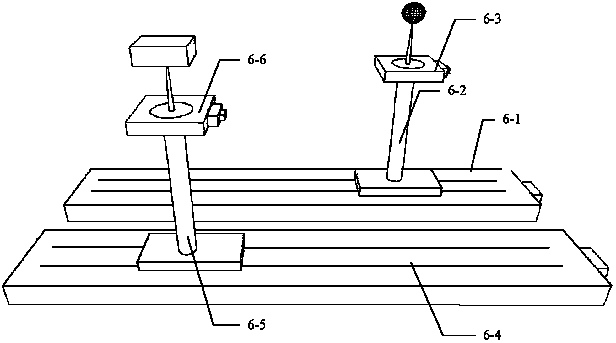
[0066] Specific implementation mode three: the following combination figure 2 Describe this embodiment, this embodiment is a further description of Embodiment 1 or 2, the precision motion platform 6 is composed of a standard target electronically controlled translation platform 6-1 and an electronically controlled translation platform 6-4 for a target to be measured,
[0067] The slides on the standard target electronically controlled translation platform 6-1 and the target electronically controlled translation platform 6-4 to be measured are parallel to each other, and the standard target fixed frame 6-2 is connected to the standard target electronically controlled translation platform 6-1 through the fixed base plate. The translation platform is connected, the standard target electric control rotary table 6-3 is fixed on the upper end surface of the standard target fixed frame 6-2, and the standard target is set on the rotary table of the standard target electric control rot...
PUM
 Abstract
Description
Claims
Application Information