Wireless energy transfer in lossy environments

A wireless power and transfer system technology, applied in antennas, power management, vehicle energy storage, etc., can solve problems such as small offset tolerance, and achieve the effect of low inherent loss rate

Active Publication Date: 2012-05-02
WITRICITY CORP
View PDF4 Cites 201 Cited by
  • Summary
  • Abstract
  • Description
  • Claims
  • Application Information

AI Technical Summary

Problems solved by technology

Traditional inductive schemes have demonstrated transfer of moderate to substantial power, however only over very short distances and with very small offset tolerances between the main power supply unit and the auxiliary receiver unit

Method used


Image

  • Wireless energy transfer in lossy environments
  • Wireless energy transfer in lossy environments
  • Wireless energy transfer in lossy environments

Examples


Embodiment Construction

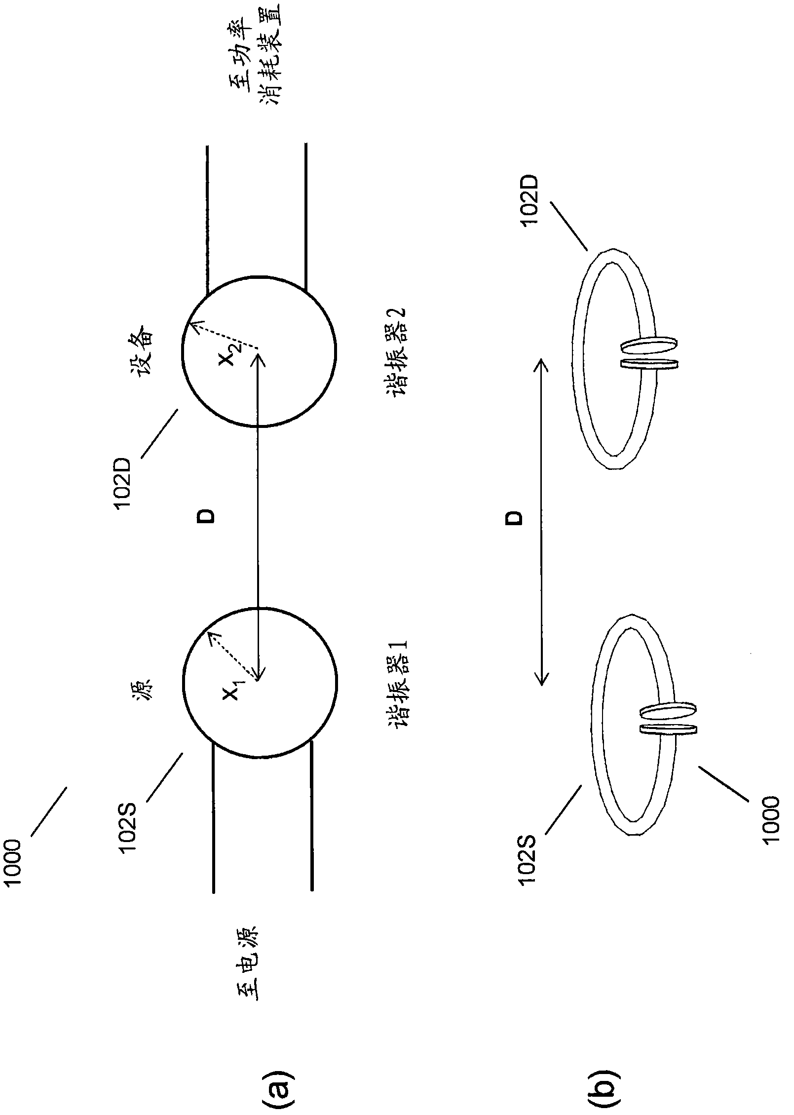
[0104] As noted above, the present disclosure relates to coupled electromagnetic resonators having long-lived oscillatory resonant modes that can wirelessly transfer power from a power source to a power sink. However, the present technique is not limited to electromagnetic resonators, but is general and can be applied to a variety of resonators and resonance objects. Therefore, we first describe the general technique and then disclose electromagnetic examples for wireless energy transfer.
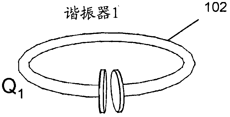
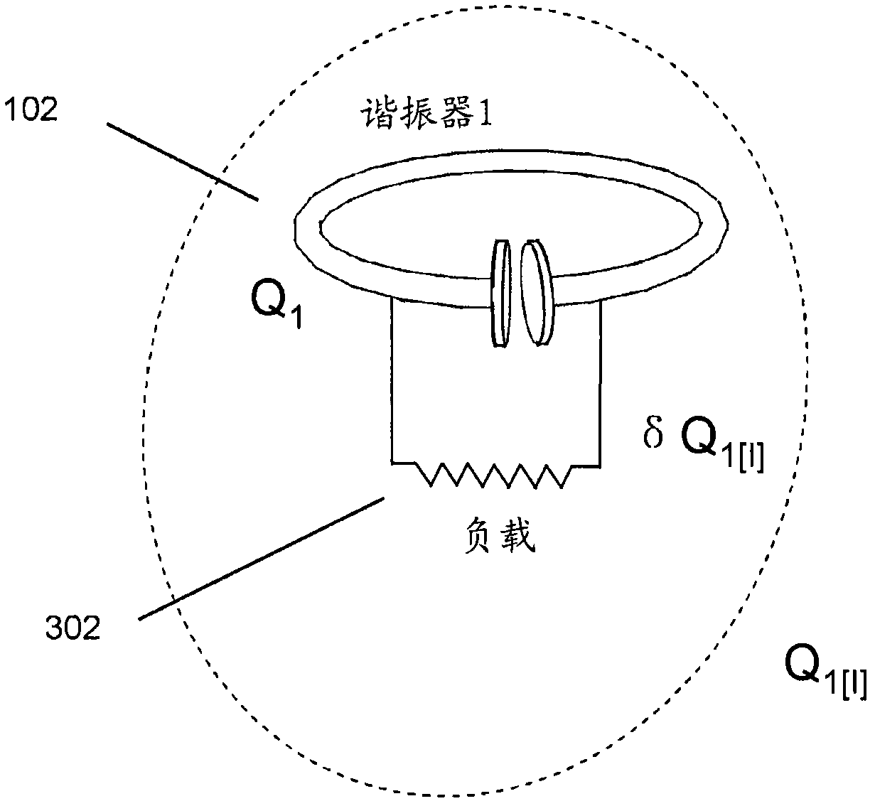
[0105] resonator

[0106] A resonator can be defined as a system capable of storing energy in at least two different forms, and in which the stored energy oscillates between the two forms. A resonance has a specific mode of oscillation with a resonant (modal) frequency f and a resonant (modal) field. The angular resonance frequency ω can be defined as ω=2πf, the resonance wavelength λ can be defined as λ=c / f, where c is the speed of light, and the resonance period T can be defined as T=1 / ...


PUM

PropertyMeasurementUnit
diameteraaaaaaaaaa
heightaaaaaaaaaa
depthaaaaaaaaaa

Abstract

Described herein are improved configurations for a wireless power transfer for electronic devices that include at least one source magnetic resonator including a capacitively- loaded conducting loop coupled to a power source and configured to generate an oscillating magnetic field and at least one device magnetic resonator, distal from said source resonators, comprising a capacitively-loaded conducting loop configured to convert said oscillating magnetic fields into electrical energy, wherein at least one said resonator has a keep-out zone around the resonator that surrounds the resonator with a layer of non-lossy material.

Description

[0001] Cross References to Related Applications [0002] This application claims priority to the following U.S. patent applications, each of which is incorporated herein by reference in its entirety: U.S. Patent Application No. 12 / 567,716 filed September 25, 2009; U.S. Patent Application No. 12 / 567,716 filed May 15, 2009 Application No. 61 / 178,508; U.S. Application No. 61 / 182,768, filed June 1, 2009; U.S. Application No. 61 / 156,764, filed March 2, 2009; U.S. Application No. 61 / 152,390, filed February 13, 2009 ; U.S. Application No. 61 / 163,695, filed March 26, 2009; U.S. Application No. 61 / 172,633, filed April 24, 2009; U.S. Application No. 61 / 169,240, filed April 14, 2009; April 2009 U.S. Application No. 61 / 173,747, filed December 29; U.S. Patent Application No. 12 / 639,489, filed December 16, 2009; and U.S. Application No. 12 / 647,705, filed December 28, 2009. [0003] background technical field [0004] The present disclosure relates to wireless energy transfer, also known a...

Claims


Application Information

Patent Timeline
Patent Type & Authority Applications(China)
IPC IPC(8): H01F27/42
CPCH03H7/40B60L2210/10B60L2210/20B60L2210/30B60L2210/40B60L2250/10B60L2250/16B60L2260/32H01F27/02H01F27/34H01F38/14H01F2003/005H01Q1/248H04B5/0012H04B5/0037H04B5/0075H04B5/0081Y02T90/14Y04S10/126Y04S30/14B60L2200/26B60L53/64B60L55/00B60L53/63B60L53/65B60L53/665B60L53/51B60L53/52H02J7/35B60L53/122B60L53/124B60L53/126Y02E60/00Y02T10/72Y02T10/7072Y02T90/12Y02T90/167Y02T10/70H02J50/90H02J50/12H02J50/50H02J50/40H02J50/80H02J50/60H02J50/70H04B5/0031
Inventor A·B·科斯K·L·霍尔M·P·克斯勒M·索尔亚奇克E·R·吉勒
Owner WITRICITY CORP
Why Eureka
Try Eureka