An optical device coupling device, an ultraviolet curing device, and an ultraviolet curing method

A coupling device and curing device technology, which is applied in the coupling of optical waveguides, optical components, instruments, etc., can solve the problems of low production efficiency, dependence, and poor consistency of product optical indicators in manual coupling, and achieve high product consistency and reliability. , short optical path coupling time and high coupling efficiency

Active Publication Date: 2020-06-30
GUANGXUN SCI & TECH WUHAN
View PDF13 Cites 0 Cited by
  • Summary
  • Abstract
  • Description
  • Claims
  • Application Information

AI Technical Summary

Problems solved by technology

[0006] The technical problem solved by the present invention is that in the prior art, the manual adjustment of optical path coupling is completely relied on, the production efficiency of manual coupling is low, and the consistency of product optical indicators is poor.

Method used


Image

  • An optical device coupling device, an ultraviolet curing device, and an ultraviolet curing method
  • An optical device coupling device, an ultraviolet curing device, and an ultraviolet curing method
  • An optical device coupling device, an ultraviolet curing device, and an ultraviolet curing method

Examples


Embodiment 1

[0045]An optical device coupling device provided by the present invention is applied to devices such as dielectric film filters, gain compensation filters, and temperature compensation gain compensation filters. These devices are all optical paths between collimators and collimators Coupling, further, can also be applied to the coupling of a collimator and a TO-packaged optical chip, and further, the optical device coupling device is suitable for angular optical path coupling.

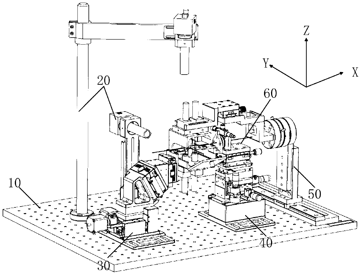
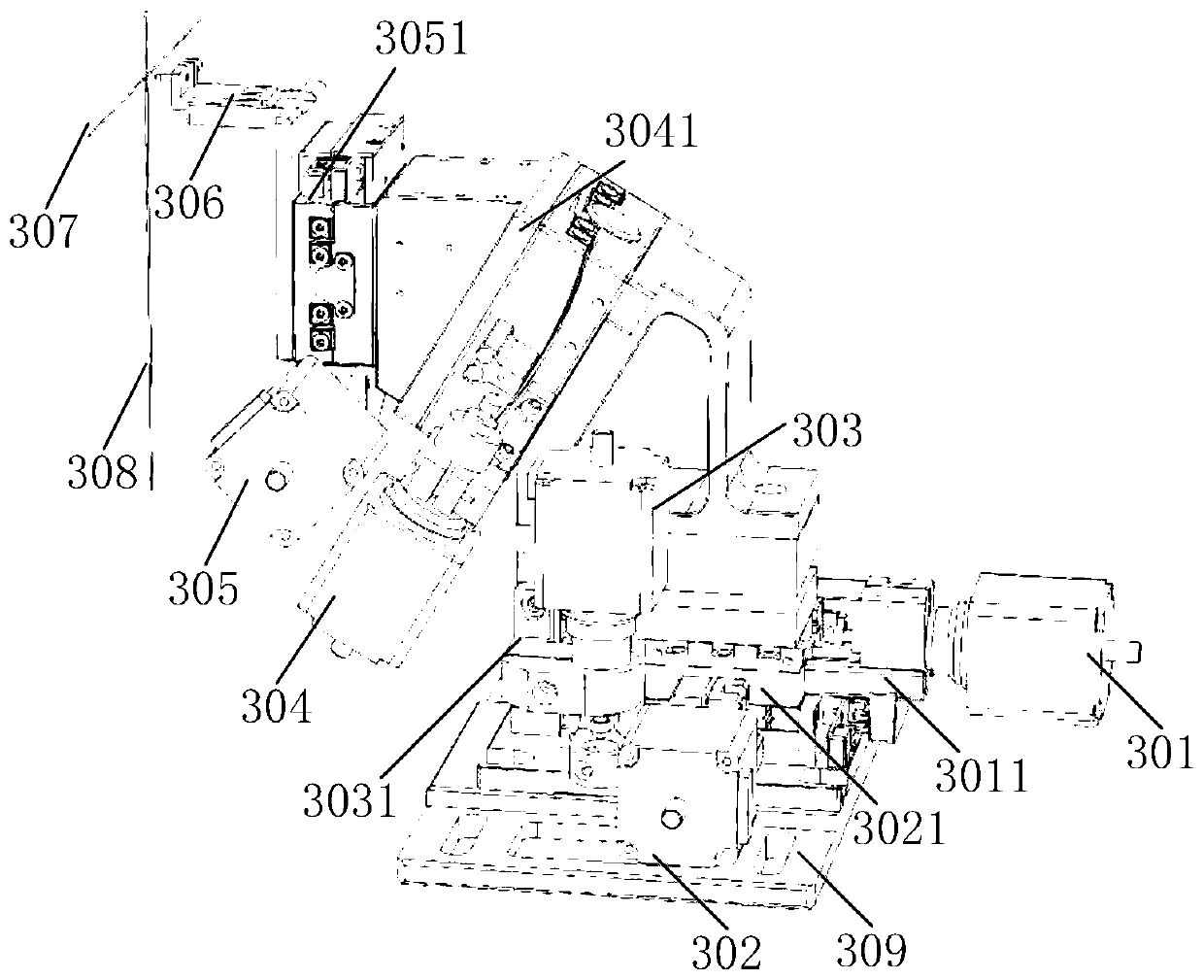
[0046] Embodiment 1 of the present invention provides an optical device coupling device, such as Figure 1 to Figure 3 As shown, it includes an electric adjustment module 30, a manual fine-tuning frame module 40 and a corner module 60; the electric adjustment module 30 is provided with an electric adjustment unit and a first clamp module 306, and the first clamp module 306 is arranged on the electric adjustment On the unit; the corner module 60 is arranged on the manual fine-tuning frame module 40, and...

Embodiment 2

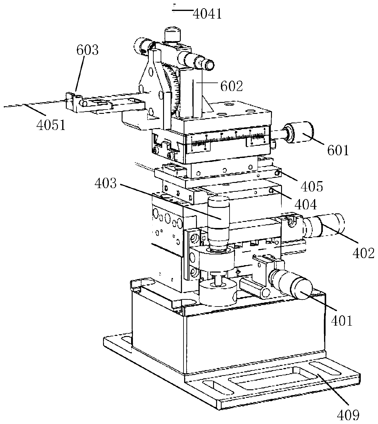
[0065] Embodiment 2 of the present invention provides an ultraviolet curing device, such as figure 1 and Figure 4 As shown, it includes the optical device coupling device provided in Embodiment 1 of the present invention, and an ultraviolet curing module 50 . The optical device coupling device is used to realize the optical path coupling of the first coupling device and the second coupling device, and the ultraviolet curing module 50 is used for coupling the first coupling device and the second coupling device The dispensing position of the device tube base 512 is UV cured.

[0066] Described ultraviolet curing device 50 comprises ultraviolet curing lamp head (such as Figure 4 The corresponding reference numeral 508 shown, the object of reference numeral 509) and the UV curing THX rotation shaft 504; UV curing is performed at the glue position; the UV curing THX rotation axis 504 is used for angular rotation according to the deflection directions of the UV irradiation win...

Embodiment 3

[0081] Embodiment 3 of the present invention provides an ultraviolet curing method, which is suitable for the ultraviolet curing device provided in Embodiment 2 of the present invention. like Figure 5 Shown, described ultraviolet curing method comprises the following steps:

[0082] Step S100: Reset the electric adjustment module, and adjust the manual fine-tuning frame module to an initial position.

[0083] The electric adjustment module 30 resets automatically under the control of the host computer, and manually adjusts the manual fine adjustment frame module 40 to the initial position.

[0084] Step S200: installing the first coupling device on the first fixture module, and installing the second coupling device on the second fixture module.

[0085] The first clamp module 306 is used to clamp the first coupling device, and the second clamp module 603 is used to clamp the second coupling device. The present invention can design the second coupling device according to the...


PUM


Abstract

The invention discloses optical member coupling equipment and an ultraviolet curing device and method. The moving position of a first coupling member which is clamped by a first fixture module is automatically adjusted by an electric adjusting module, a turning module is arranged on a manual fine adjusting frame module, the turning module is provided with a second fixture module, the second fixture module is used for clamping a second coupling member, and the initial position of the second coupling instrument is adjusted by the manual fine adjustment frame module. By automatically adjusting the moving position of the first coupling member through the second fixture module to perform optical path coupling with the second coupling member, the optical member coupling equipment has the advantages that the optical path coupling time is shorter and the coupling efficiency is higher when light searching is conducted by the optical member coupling equipment compared with the manner which completely depends on manual coupling, and the uniformity and reliability of products manufactured by the optical member coupling equipment.

Description

【Technical field】 [0001] The invention relates to the field of optical device manufacturing, in particular to an optical device coupling device, an ultraviolet curing device and an ultraviolet curing method. 【Background technique】 [0002] Dielectric thin film filters (Thin Film Filters, TFF), gain flat filters (Gain Flat Filters, GFF) and other types of devices have a wide range of applications in optical wavelength division multiplexing, gain compensation in the optical path, etc. Filter products with different functional types. These devices all have a common feature: the light is input through the collimator, and then output through the collimator. The coupling production of this type of device belongs to the coupling between two collimators. [0003] For the coupling between two collimators, the coupling loss of the analytical device can be directly analyzed by Gaussian beams. The optical field superposition between the two collimators has the following mismatch forms...

Claims


Application Information

Patent Timeline
Patent Type & Authority Patents(China)
IPC IPC(8): G02B6/26G02B27/62
CPCG02B6/26G02B27/62
Inventor 楚劲草谭书伟曾睿龚垒杨波
Owner GUANGXUN SCI & TECH WUHAN
Why Eureka
Try Eureka