Laboratory hydraulic system

A hydraulic system, laboratory technology, applied in the direction of laboratory stools/laboratory benches, educational appliances, instruments, etc., can solve the problem of no teaching needs students' course experiments, etc., to achieve the effect of complete functions

Inactive Publication Date: 2012-05-09
大连维乐液压制造有限公司
View PDF4 Cites 2 Cited by
  • Summary
  • Abstract
  • Description
  • Claims
  • Application Information

AI Technical Summary

Problems solved by technology

[0002] In the prior art, there is no laboratory hydraulic system that can meet the teaching needs of the school and the course tests of the students, and can also test and inspect the performance and parameters of various hydraulic components, hydraulic pumps, and hydraulic systems.

Method used


Image

  • Laboratory hydraulic system
  • Laboratory hydraulic system
  • Laboratory hydraulic system

Examples


Embodiment Construction

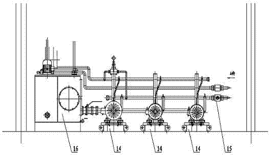
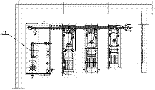
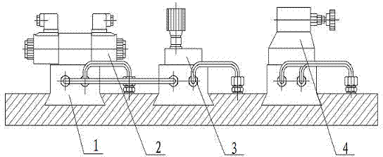
[0013] Such as Figure 1-Figure 5 As shown, the laboratory hydraulic system consists of two parts: a test bench and a power source. The test bench includes a plate valve test bench, a superimposed valve test bench and a cartridge valve test bench. The plate valve test bench mainly consists of a socket bottom plate 1, an electromagnetic The reversing valve 2, the plate type throttle valve 3 and the plate type overflow valve 4 are composed. The electromagnetic reversing valve 2, the plate type throttle valve 3 and the plate type overflow valve 4 are respectively set on the socket type bottom plate 1. The superposition valve test bench mainly It is composed of a socket type passage body 5, a superposition type overflow valve 6, a superposition type throttle valve 7 and an electromagnetic directional valve 8. The superposition type overflow valve 7 is arranged on the socket type passage body 5, and the superposition type throttle valve 7 is set on the superimposed relief valve 6, t...


PUM


Abstract

The invention discloses a laboratory hydraulic system, which comprises a test bench and a power source, wherein the test bench comprises a plate-type valve test bench, a sandwich valve test bench and a cartridge valve test bench; the plate-type valve test bench mainly comprises a socket-type bottom plate, a solenoid directional valve, a plate-type throttle valve and a plate-type overflow valve; the sandwich valve test bench mainly comprises a socket-type channel body, a stacked overflow valve, a stacked throttle valve and a solenoid directional valve; the cartridge valve test bench comprises a socket-type valve block, a cartridge throttle valve, a cartridge valve, a solenoid directional valve and a cartridge overflow valve; the power source comprises a plurality of oil supply devices, an oil tank and a circulating cooling device. According to the laboratory hydraulic system disclosed by the invention, the functions of the test bench are more perfect and more compact; different hydraulic loops or systems can be conveniently, simply and quickly formed according to different teaching requirements and experiment requirements so as to satisfy the requirements of various experiments and checkouts.

Description

Technical field [0001] The invention relates to a laboratory hydraulic system. Background technique [0002] In the prior art, there is no laboratory hydraulic system that can not only meet the teaching needs of schools and students' course tests, but also perform tests and inspections of various hydraulic components, hydraulic pumps, hydraulic system performance, and parameters. Summary of the invention [0003] The purpose of the present invention is to provide a laboratory hydraulic system. [0004] The technical solution adopted by the present invention to achieve the above objective is: a laboratory hydraulic system, the system is composed of a test bench and a power source, the test bench includes a plate valve test bench, a superimposed valve test bench and a cartridge Valve test bench, said plate valve test bench is mainly composed of socket type bottom plate, electromagnetic directional valve, plate type throttle valve and plate type overflow valve. The electromagnetic dir...

Claims


Application Information

Patent Timeline
Patent Type & Authority Applications(China)
IPC IPC(8): B01L9/02G09B23/12
Inventor 张久海丁维力
Owner 大连维乐液压制造有限公司
Why Eureka
Try Eureka