Concrete composite shear wall

A combined shear wall and concrete technology, applied in the direction of walls, building components, earthquake resistance, etc., can solve the problems of increase, the overall control of the structure, the cost increase, etc., to achieve a clear force transmission mechanism, conducive to theoretical analysis, high bearing capacity Effect

Inactive Publication Date: 2012-05-09
SOUTH CHINA UNIV OF TECH
View PDF5 Cites 17 Cited by
  • Summary
  • Abstract
  • Description
  • Claims
  • Application Information

AI Technical Summary

Problems solved by technology

In addition, due to the requirements of the code for the calculation of the shear-weight ratio and the floor shear force borne by the outer frame columns, when the thickness of

Method used


Image

  • Concrete composite shear wall
  • Concrete composite shear wall
  • Concrete composite shear wall

Examples


Embodiment 1

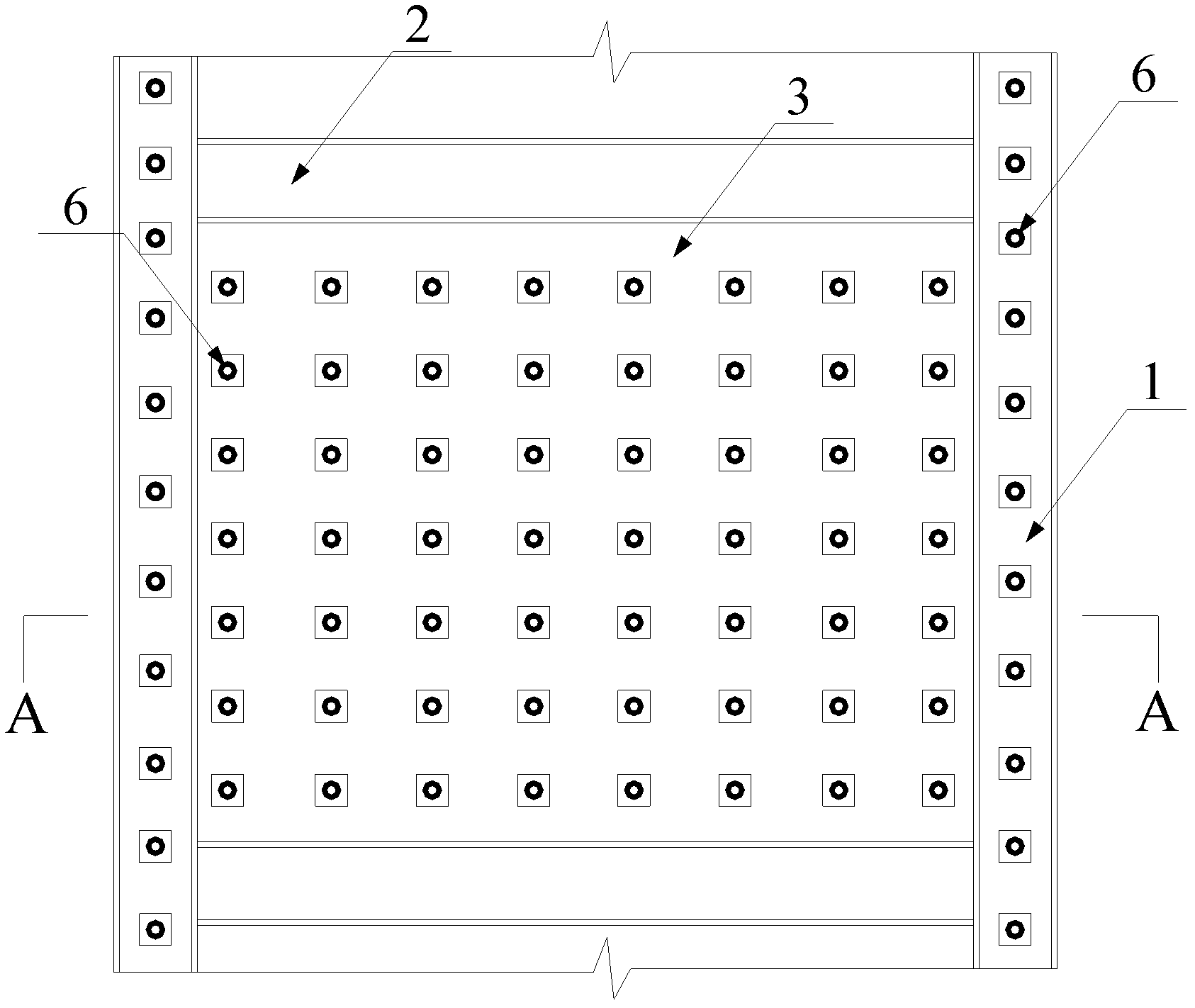
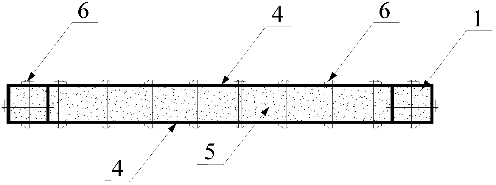
[0027] Such as figure 1 , figure 2 As shown, the concrete composite shear wall of the present invention includes a body of wall and a side column, and the body of wall is fixedly connected with the side column, and the body of wall 3 includes an array of tie rods 6 and a double-layer metal plate 4. The double-layer metal plate 4 constitute a sandwich, and a concrete wall panel 5 is arranged in the sandwich, and the constraint tie rod array 6 passes through the double-layer metal plate 4, and the concrete wall panel 5 is fastened to the sandwich of the double-layer metal plate 4 through the constraint tie rod array 6 Inside. Double-layer metal plate 4 adopts steel plate.

[0028] The distribution form of the constraining tie rod array 6 is a side-by-side array arrangement.

[0029] The side column is a steel tube concrete side column 1 composed of a steel pipe and a concrete column therein, and the steel tube of the steel tube concrete side column 1 is welded and fixed to t...

Embodiment 2

[0034] This embodiment is the same as Embodiment 1 except for the following features.

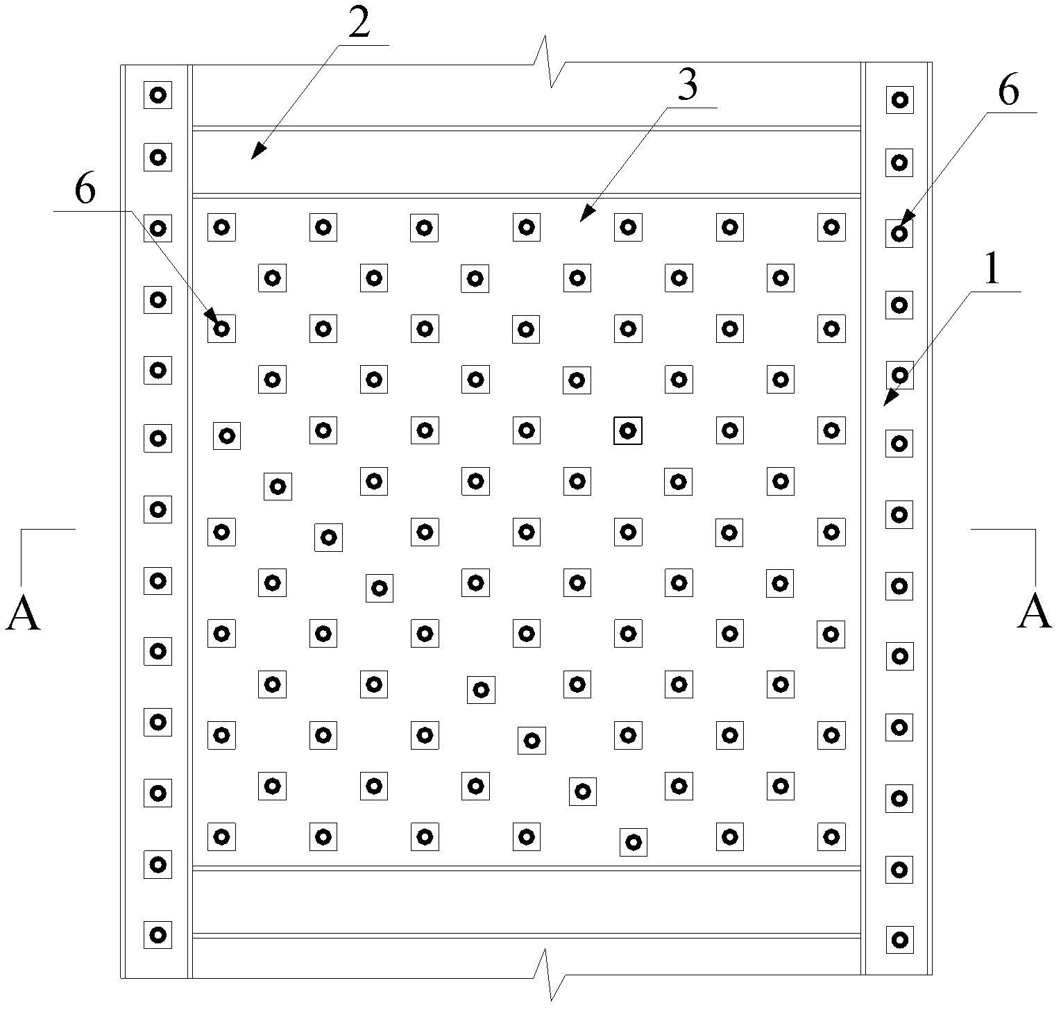
[0035] Such as image 3 , Figure 4 As shown, the distribution form of the constraining rod array 6 is a quincunx array arrangement.

Embodiment 3

[0037] This embodiment is the same as Embodiment 1 except for the following features.

[0038] Such as Figure 5 , Figure 6 as shown,

[0039] The cross-sectional shape of the steel pipe concrete side column 1 is circular.


PUM


Abstract

The invention discloses a concrete composite shear wall, which includes a wall body and side columns, wherein the wall body is fixedly connected with the side columns. The wall body comprises a binding bar array and double-layer metal plates; interlayer is formed between the double-layer metal plates; concrete wallboards are arranged in the interlayer, the binding bar array penetrates the double-layer metal plates, and the concrete wallboards are tightly fixed inside the double-layer metal plates through the binding bar array; the binding bar array is distributed in block form or in quincuncial form; the side columns are steel pipe concrete side columns formed by steel pipes and concrete columns in the steel pipes; the steel pipes of the steel pipe concrete side columns are welded and fixed with the double-layer metal plates. The concrete composite shear wall has high bearing capacity, excellent seismic resistance, high ductility, reasonable stress and the like, thereby being suitable for high level and super high level core tube shear walls.

Description

technical field [0001] The invention relates to the technical field of building structures, in particular to a concrete composite shear wall. Background technique [0002] In recent years, with the rapid development of social economy and the continuous improvement of construction technology, more and more high-rise and super high-rise large complex buildings have sprung up. At present, the hybrid structure system often used in super high-rise buildings is a new structure system with good wind resistance, earthquake resistance and good economy. However, since the shear walls of the core tube of the hybrid structure often bear more than 80% of the seismic shear force, and some even bear the entire shear force, the frame only bears the vertical force, and the shear-span ratio of the shear wall at the bottom of the structure is generally small. At the same time, the axial compression ratio is very large, so the seismic performance of the entire structural system depends to a la...

Claims


Application Information

Patent Timeline
IPC IPC(8): E04B2/56E04B2/58E04B2/64E04B1/98
Inventor 蔡健刘鸿亮杨春陈庆军姜正荣
Owner SOUTH CHINA UNIV OF TECH
Why Eureka
Try Eureka