Micro-oil ignition burner

A technology for igniting a burner and a small amount of oil, which is applied to burners, burners for burning powder fuel, and combustion methods, etc. problems, to achieve the effect of wide adaptability of coal types, high cost performance, moderate investment and operating costs

Active Publication Date: 2012-05-09
SHANGHAI BOILER WORKS
View PDF5 Cites 7 Cited by
  • Summary
  • Abstract
  • Description
  • Claims
  • Application Information

AI Technical Summary

Problems solved by technology

At present, there are a large number of successful application examples of micro-oil ignition in domestic power plant boilers that use bituminous coal as power coal. Pulverized coal airflow is easily ignited
However, the low-volume ignition technology has poor adaptability to coal types with low volatile content such as anthracite, lean coal, and low-quality bituminous coal. The micro-oil ignition technology used in domestic lean-coal boilers is basically the supply of large and small oil guns. Only when the amount of oil is used in the oven can it be ignited. As a result, it loses the meaning of saving fuel by igniting with a small amount of oil
[0005] Second, when the micro-oil ignition technology is used, the combustion of oil requires air distribution, which consumes oxygen, and it is easy to "grab oxygen" from the primary air, which makes it difficult for the primary air to ignite the pulverized coal airflow.

Method used


Image

  • Micro-oil ignition burner
  • Micro-oil ignition burner
  • Micro-oil ignition burner

Examples


Embodiment 1

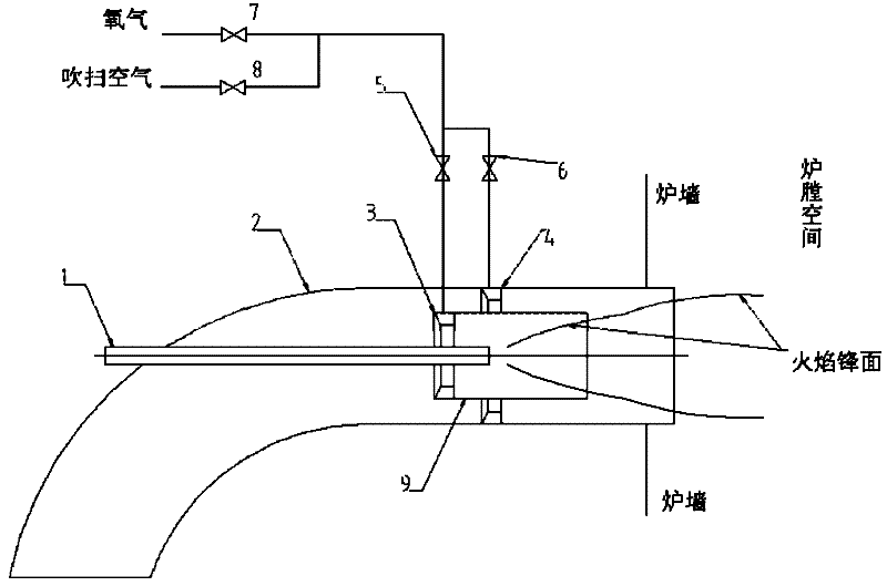
[0023] refer to figure 1 , image 3 with Figure 4 , a micro-oil ignition burner in an oxygen-enriched environment of the present invention includes a micro-oil gasification small oil gun 1 and a burner 2. The burner 2 contains a sleeve 9, and the micro-oil gasification small oil gun 1, the burner 2 and the sleeve 9 are arranged coaxially. The first oxygen conduit 3 is installed on the inner wall facing the direction of the pulverized coal flow at the left end of the sleeve 9. In addition to providing oxygen, the first oxygen conduit 3 also acts as a coal powder concentration ring. The outer side of the pipe wall in the direction of the pulverized gas flow is surfacing with wear-resistant metal, and the first oxygen conduit 3 is arranged with axially rotating blades on the pipe wall away from the direction of the pulverized coal flow. A local oxygen-enriched zone is formed in the sleeve 9 and adjacent areas. The second oxygen conduit 4 is installed on the inner wall of the...

Embodiment 2

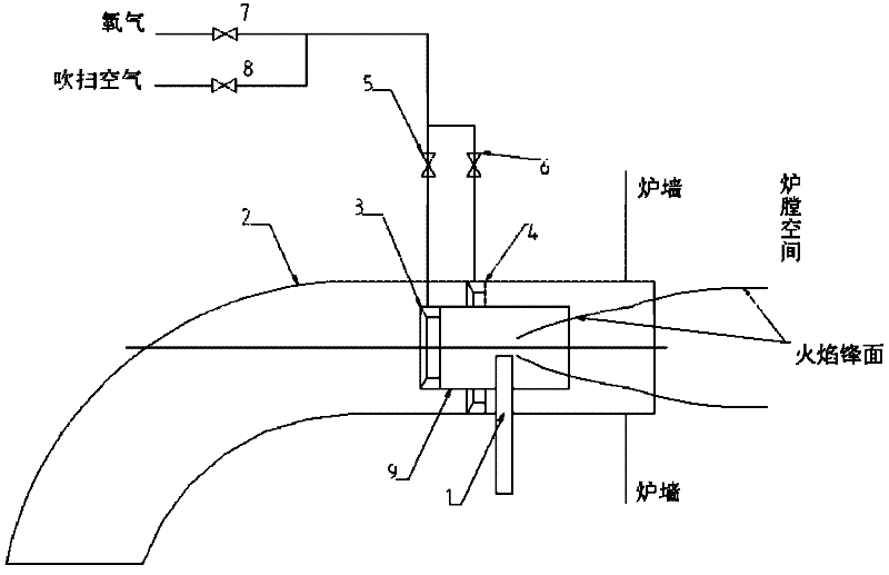
[0027] refer to figure 2 , image 3 with Figure 4 , The difference between this embodiment and Embodiment 1 is that the small oil gasification oil gun 1 is inserted into the burner 2 from the radial direction of the burner 2, and the high-temperature smoke of the vaporized oil mist ejected from the small oil gasification oil gun Air can be filled in the sleeve 9.

Embodiment 3

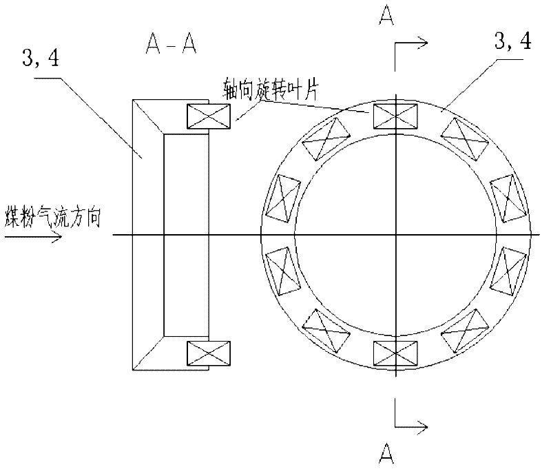
[0029] refer to image 3 As shown, in this embodiment, the cross-sectional shape of the oxygen conduit is trapezoidal, and its wall facing the direction of the pulverized coal flow is surfacing with anti-wear metal or anti-wear ceramics. Axial rotating blades are arranged on the wall facing away from the gas flow direction of the pulverized coal, and oxygen enters the burner in a swirling flow and is mixed with the pulverized coal.


PUM


Abstract

The invention discloses a micro-oil ignition burner, comprising a small micro-oil-gasification oil gun and a burner, wherein the burner internally comprises at least one coaxial or non-coaxial sleeve, two oxygen guiding pipes are installed in the burner, one oxygen guiding pipe is installed on the inner wall of the sleeve facing the direction of air flow of pulverized coal, the other oxygen guiding pipe is installed on the inner wall of the burner, oxygen can enter the burner and the annular space of the sleeve through the oxygen guiding pipes, and oxygen-rich zones are formed in the burner and the flowing space of the air flow of the pulverized coal in the boiler so as to enhance the burning of the air flow of the pulverized coal.

Description

technical field [0001] The invention belongs to the field of thermal boilers, and relates to boiler accessories, in particular to an ignition burner with a small amount of oil. Background technique [0002] The traditional way of igniting boilers in power plants is oil gun ignition. When the boiler is ignited, the fuel gun is first lit. After the oil burns in the furnace for a certain period of time, the furnace is heated to the ignition temperature of the pulverized coal flow. At this time, the pulverized coal is blown into the furnace for mixed combustion of oil and coal. When the load of the boiler reaches more than 50% and the pulverized coal flow can burn stably, the fuel oil is gradually cut off to complete the ignition and start-up process of the boiler. In order to save costs and reduce the fuel oil consumption of power plant boilers, many domestic companies have developed micro-fuel ignition technology, which has been widely used in many power plant boilers. [00...

Claims


Application Information

Patent Timeline
Patent Type & Authority Applications(China)
IPC IPC(8): F23D1/00F23D1/02
CPCY02E20/34
Inventor 郑路张建文陈飞张翔
Owner SHANGHAI BOILER WORKS
Why Eureka
Try Eureka