Method for monitoring of steel bar corrosion in real time

A real-time monitoring and steel corrosion technology, applied in the field of sensing, can solve the problems that bare fiber grating is not suitable for extensive construction of civil engineering, is not suitable for long-term monitoring of steel corrosion, and has shortened life. The effect of prolonging the service life

Inactive Publication Date: 2012-05-09
SHENYANG JIANZHU UNIVERSITY
View PDF3 Cites 23 Cited by
  • Summary
  • Abstract
  • Description
  • Claims
  • Application Information

AI Technical Summary

Problems solved by technology

However, because the bare fiber grating is wound and pasted on the steel bar, the bare fiber grating is in a bent state for a long time, and its life is shortened. It is not suitable for long-term monitoring of steel bar corrosion, and the bare fiber grating is not suitable for the extensive construction of civil engineering, and its practicability is poor.

Method used


Image

  • Method for monitoring of steel bar corrosion in real time
  • Method for monitoring of steel bar corrosion in real time
  • Method for monitoring of steel bar corrosion in real time

Examples


Embodiment 1

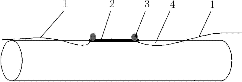
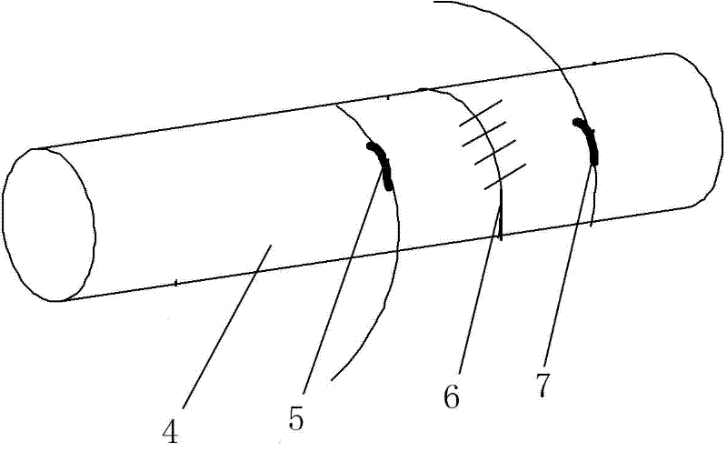
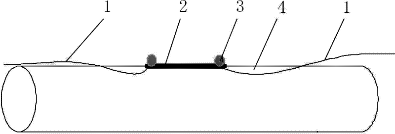
[0028] Such as figure 1 As shown, the method for real-time monitoring of steel corrosion includes the following steps:

[0029] (a) First, coat the surface of the fiber grating strain sensor 2 packaged in steel pipe with a layer of rust conversion paint, and the coating environment is controlled at a temperature of 25°C and a relative air humidity of 80%;

[0030] (b) In order to ensure that the fiber grating strain sensor 2 encapsulated in the steel pipe can fully contact the surface of the steel bar 4 and avoid measurement errors caused by strain transfer, the surface of the steel bar 4 is firstly ground with a grinder, and then further polished with sandpaper to make the steel bar 4 The surface is smoother and smoother. In order to prevent the influence of pollutants such as grinding debris, use absorbent cotton balls dipped in absolute alcohol to scrub the polished area and set aside;

[0031] (c) Paste the fiber grating strain sensor 2 encapsulated in the steel pipe obt...

Embodiment 2

[0034] (a) First, coat the surface of the fiber grating strain sensor 2 packaged in steel pipe with a layer of rust conversion paint. The coating environment is controlled at a temperature of 5°C and a relative air humidity of 60%.

Embodiment 3

[0036](a) First, coat the surface of the fiber grating strain sensor 2 packaged in steel pipe with a layer of rust conversion paint, and the coating environment is controlled at a temperature of 40°C and a relative air humidity of 20%; the rest is the same as in Embodiment 1, and will not be repeated.


PUM


Abstract

The invention discloses a method for real-time monitoring of steel bar corrosion. The method comprises the following steps: (a) coating a layer of rust conversing paint on a surface of a steel pipe packaged fiber grating strain sensor and controlling a temperature in a coating environment at 0-40 DEG C and an air relative humidity at no more than 80%; (b) polishing a surface of a selected steel bar by a grinder to realize a flattening and smooth surface and keeping for usage; (c) pasting the steel pipe packaged fiber grating strain sensor obtained from the step (a) on a polished position of the steel bar to be used in the step (b); and (d) carrying out real-time monitoring on a wavelength drift amount by a fiber grating demodulator, meanwhile laying a steel pipe packaged fiber grating temperature sensor for monitoring change of temperature and completing temperature compensation. The invention can not only monitor early stage steel bar corrosion in a structure but also have good protection effect on the fiber grating sensor during a monitoring process and have strong realizability.

Description

technical field [0001] The invention relates to an early monitoring method for steel bar corrosion in structural engineering, in particular to a method for real-time monitoring of steel bar corrosion. It belongs to the field of sensor technology. Background technique [0002] In 1978, K.O. Hill of the Canadian Communication Research Center produced the world's first fiber Bragg grating. In 1989, G. Meltz of United Technology Research Center in the United States realized the UV laser side writing technology of fiber Bragg grating (FBG), which made a breakthrough in the production technology of fiber Bragg grating. After that, researchers from Japan, the United States, Germany and many other countries have successively studied the application of fiber optic sensing systems in civil engineering. So far, fiber gratings have been widely used in many aspects in many fields. Compared with traditional sensors, fiber grating sensors have more advantages: small size, light weight, g...

Claims


Application Information

Patent Timeline
Patent Type & Authority Applications(China)
IPC IPC(8): G01N21/88
Inventor 孙丽孙茜茜
Owner SHENYANG JIANZHU UNIVERSITY
Why Eureka
Try Eureka