Heat radiator

A heat sink and heating element technology, applied in the direction of electric solid devices, semiconductor devices, semiconductor/solid device components, etc., can solve the problem of insufficient heat removal effectively

Inactive Publication Date: 2012-05-09
JOINSET +1
View PDF5 Cites 15 Cited by
  • Summary
  • Abstract
  • Description
  • Claims
  • Application Information

AI Technical Summary

Problems solved by technology

However, the related technology is not enough to effectively remove the heat

Method used


Image

  • Heat radiator
  • Heat radiator
  • Heat radiator

Examples


Embodiment Construction

[0052] Preferred embodiments of the present invention will now be described in detail with reference to the accompanying drawings.

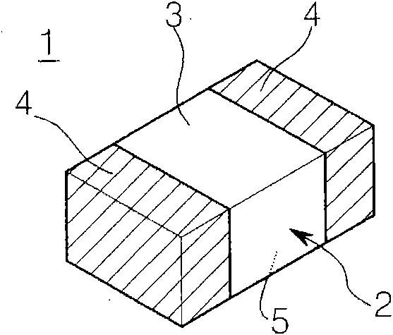
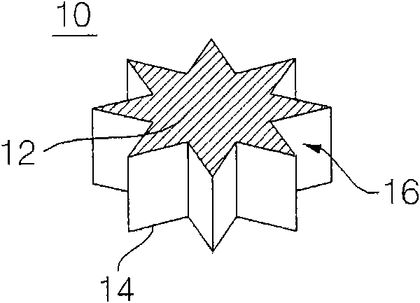
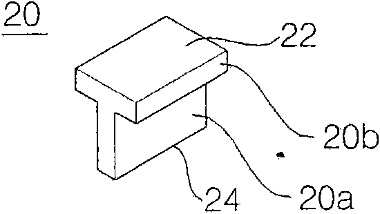
[0053] Figure 1A , Figure 1B with Figure 1C are perspective views respectively showing different heat sinks 1, 10 and 20 according to embodiments of the present invention.

[0054] Such as Figure 1A As shown in , the heat sink 1 has a three-dimensional (3D) rectangular shape. The heat sink 1 includes: a horizontal back 5 and a front 3; a main body 2 made of thermally conductive ceramics or carbonaceous materials. A metal layer 4 surrounds both sides of the body 2 in order to be able to apply reflow soldering to the solder paste. However, the heat sink 1 is not limited to the above structure, and the metal layer 4 may be formed only on the rear surface of the main body 2 . The heat sink 1 can be reflow soldered to solder paste through the metal layer 4 formed at least on the back side.

[0055] The heat sink 1 according to the present emb...


PUM


Abstract

The invention relates to a heat radiator, which is characterized in that: the heat radiator can be surface mounted, the heat radiator is in a three-dimensional shape and comprises a main body which is made of metal, the main body is provided with a horizontal back surface and at least partial horizontal front surface, so partial front surface can be mounted on a conductive pattern of the printed circuit board (PCB) through alignment, and the back surface can be attached to the conductive pattern through backflow welding.

Description

technical field [0001] The present invention relates to a heat sink, and more particularly to a heat sink whose front side is taken and surface-mounted and whose back side is reflowed by solder paste A conductive pattern soldered to a printed circuit board (PCB). [0002] In addition, the present invention relates to a small heat sink capable of more effectively dissipating and cooling heat generated from a heat generating element via a conductive pattern of a PCB disposed adjacent to the heat generating element, and capable of being easily mounted at a low cost on a conductive pattern. Background technique [0003] Recently, the size and weight of portable electronic communication devices (eg, mobile phones) have decreased while data processing speed and capabilities have increased. Accordingly, a large amount of heat is generated from the semiconductor chip that provides the main functions of the device, which deteriorates the performance of the semiconductor chip (eg, r...

Claims


Application Information

Patent Timeline
IPC IPC(8): H01L23/36H01L23/367H05K1/02H05K1/18
CPCH01L2924/0002H01L2924/00
Inventor 金善基
Owner JOINSET
Why Eureka
Try Eureka