Exposure apparatus

An exposure device and an exposed technology, which are applied in photolithography exposure devices, microlithography exposure equipment, optics, etc., can solve the problems of natural vibration frequency reduction, inability to solve flatness, and adverse effects of exposure accuracy, etc., to improve exposure The effect of precision

Active Publication Date: 2012-05-09
V TECH CO LTD
View PDF13 Cites 14 Cited by
  • Summary
  • Abstract
  • Description
  • Claims
  • Application Information

AI Technical Summary

Problems solved by technology

The deflection of the mask M is the main cause of variation in the gap between the mask M and the substrate, which may adversely affect exposure accuracy.
However, in the exposure apparatus of Patent Document 1, there is a problem that a change in flatness (deflection) caused by changing a mask with a different size cannot be solved.
[0017] In addition, in the mask holding mechanism of the exposure apparatus disclosed in Patent Document 3, the pitch of the chuck parts provided on the long side of the mask is set to 0.65 to 0.80 times the length of the long side, which suppresses mounting on the mask. The natural vibration frequency of the mask of the mask holder is lowered, and the flatness of the deflection due to the self-weight of the mask having different sizes cannot be kept constant regardless of the size, so there is room for improvement

Method used


Image

  • Exposure apparatus
  • Exposure apparatus
  • Exposure apparatus

Examples


no. 1 approach

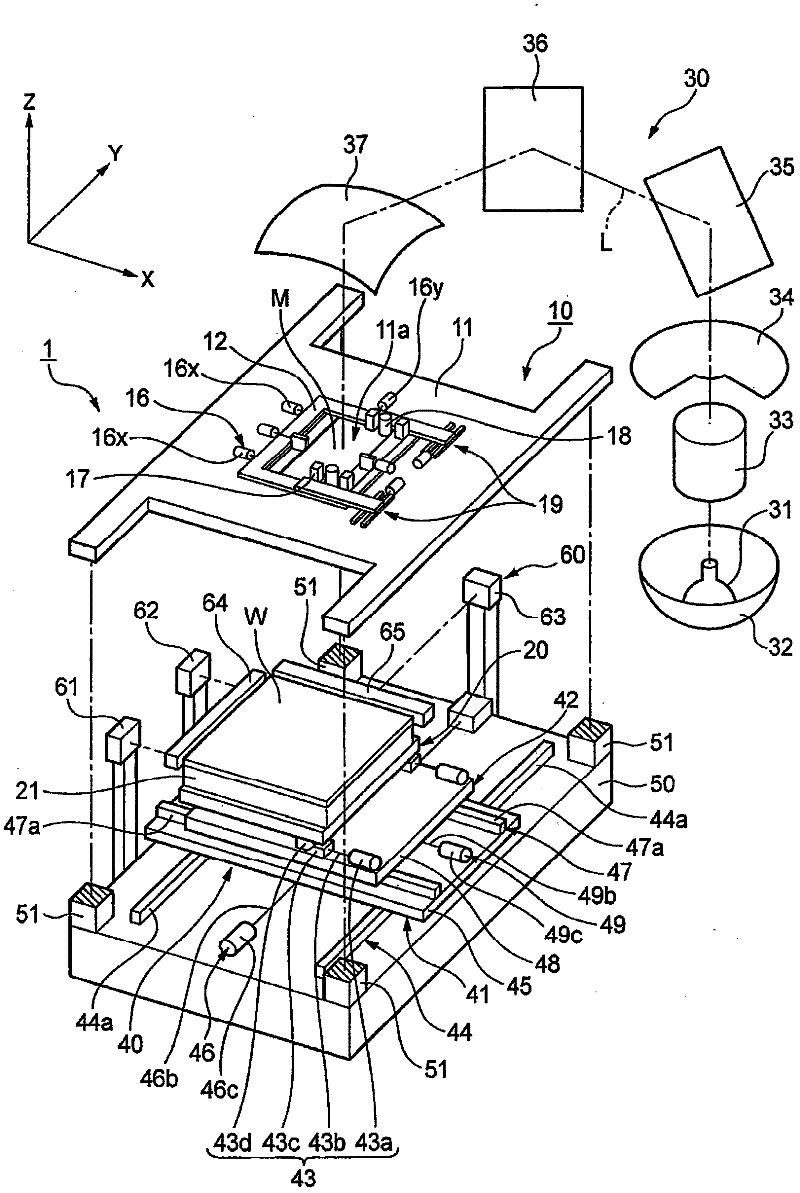
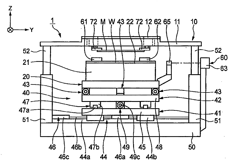
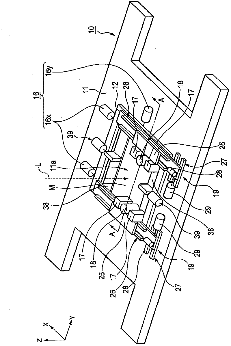
[0110] figure 1 It is a perspective view of main parts of an exposure apparatus as a first embodiment of the present invention, figure 2 is the main view, image 3 is an enlarged view of the portion near the mask table, Figure 4 is a top view of the mask table.

[0111] Such as figure 1 As shown, the exposure apparatus 1 of this embodiment has: a mask stage 10 for holding a mask M; a substrate stage 20 for holding a glass substrate (material to be exposed) W; and an illumination optical system as an irradiation mechanism for pattern exposure. 30. The substrate stage moving mechanism 40, which moves the substrate stage 20 in the X-axis, Y-axis, and Z-axis directions, and adjusts the inclination of the substrate stage 20; and a device for supporting the mask stage 10 and the substrate stage moving mechanism 40 Base 50.

[0112] In addition, the glass substrate W (hereinafter simply referred to as "substrate W") is disposed opposite to the mask M, and the mask pattern dr...

no. 2 approach

[0162] Figure 12 It is a figure which shows the exposure apparatus of 2nd Embodiment which differs from 1st Embodiment in a tilt angle adjustment mechanism. In the exposure apparatus 1 of this embodiment, the inclination angle adjustment mechanism 80 is arrange|positioned between the mask holding frame 12 and the guide rail 73a.

[0163] According to such exposure apparatus 1, similarly to 1st Embodiment, it is not necessary to exchange|exchange a mask holder, and it is possible to suction-hold a some mask of a different size accordingly. In addition, regardless of the size of the mask M, the inclination angle can be adjusted by the inclination angle adjustment mechanism 80, and the flatness of the mounted mask M can be corrected, and the gap between the mask M and the substrate W can be maintained at Be sure to increase exposure accuracy. In addition, in the case of the present embodiment, the height of the suction position of the movable mask holder 72 on the short side a...

no. 3 approach

[0167] Figure 14 In the exposure apparatus of the third embodiment, when the movable mask holder is tilted by the inclination angle adjusting mechanism, a mechanism for adjusting the level difference generated between the fixed mask holder and the movable mask holder is shown.

[0168] For example, if Figure 15 As shown, when adjusting the inclination angle of the movable mask holder 72, sometimes there is a height difference (step difference) between the fixed mask holder 71 and the movable mask holder 72. If the step difference is large, the rigidity of the brackets 71 and 72 is high. , therefore, a gap C is generated between the movable mask holder 72 and the mask M, which may adversely affect exposure accuracy.

[0169] Therefore, if Figure 14 As shown, in the fixed mask holder 71 and the movable mask holder 72, the upper surfaces of side edge portions 71d, 72d close to each other are notched to form thinner portions 71e, 72e than the rest. When the thin-walled porti...


PUM


Abstract

A mask stage (10) is provided with: a mask stage base (11); four mask holders (71, 72) with the ability to adhere to and hold each edge of a mask (M); linear guides (73) disposed between a pair of mask holders (72) that adhere to and hold the side of the mask stage base (11) and the short sides of the mask (M); a drive mechanism (74) that forces the mask holders (72) to move on the short side; and a tilt angle adjustment mechanism (80) that is disposed between the side of the mask stage base (11) and the sides of the mask holders (72), and has the ability to adjust the tilt angle of the mask (M). This configuration enables a plurality of masks of different sizes to be accommodated in a state in which flatness is kept constant.

Description

technical field [0001] The present invention relates to an exposure device, and more specifically, to an exposure device capable of handling a plurality of masks with different sizes and adsorption areas. Background technique [0002] TFT substrates, color filters, and plasma display panel substrates of liquid crystal display devices use an exposure device to expose and irradiate a substrate coated with photoresist through a mask, thereby converting the pattern of the mask to printed on a substrate. A suction groove is provided in the mask holder of the exposure apparatus, and the edge of the mask is vacuum-suctioned into the suction groove to hold the mask. [0003] Conventionally, the exposure of substrates with different sizes required changing the mask holder of the exposure device according to the size of the mask, but it took time to replace the mask holder, and there was a problem in terms of work efficiency. On the other hand, there are known exposure apparatuses t...

Claims


Application Information

Patent Timeline
Patent Type & Authority Applications(China)
IPC IPC(8): G03F7/20H01L21/027
CPCG03F7/70716G03F7/70783
Inventor 林慎一郎桐生恭孝户川悟松坂昌明
Owner V TECH CO LTD
Why Eureka
Try Eureka