Explosion-proof and pollution-proof drilling machine

A drilling machine and anti-pollution technology, applied in the direction of boring/drilling, drilling/drilling equipment, boring machine/drilling machine parts, etc., can solve the problems of long time consumption, failure to proceed as usual, loss of transformer oil, etc., to achieve The effects of avoiding air pollution, less workload, and avoiding waste

Active Publication Date: 2016-08-03
CRRC LUOYANG CO LTD
View PDF13 Cites 0 Cited by
  • Summary
  • Abstract
  • Description
  • Claims
  • Application Information

AI Technical Summary

Problems solved by technology

The conventional method is: pump out the transformer oil in the main transformer, and then drill holes for the body. This conventional processing method has the following disadvantages: first, the transformer oil in the main transformer is pumped out, which will lose part of the transformer oil and also pollute Secondly, the main transformer body of Shao 7 is sealed and cannot be opened or cleaned. Even if the main transformer oil is drained, there will still be a small amount of transformer oil inside the body. If sparks are accidentally generated during drilling, it will be very dangerous. It is easy to ignite the transformer oil, causing an explosion, and the danger of drilling is very high; again, the workload is heavy, the time is long, the cost is high, and the waste is large
This method has the following disadvantages: firstly, the main valve is closed, the gas and oil are stopped, and the production and life of the enterprise cannot be carried out as usual, which affects the economic benefits of the enterprise, brings a lot of inconvenience to the lives of residents, and disturbs the people; secondly, it pollutes the environment, and it is easy to ignite gas, Oil exploded, posing a serious threat to people's lives and properties; again, the workload was heavy, time-consuming, costly, and wasteful

Method used


Image

  • Explosion-proof and pollution-proof drilling machine

Examples


Embodiment Construction

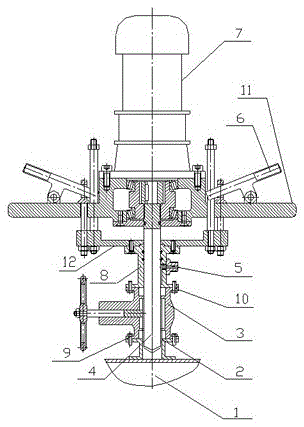
[0011] Such as figure 1 shown. The present invention mainly includes a connecting flange 2, a gate valve 3, a twist drill 4, two inlet and exhaust ports 5, a fixed bracket 11, a movable bracket 12, two control handles 6, an explosion-proof motor 7, and a docking flange 8. The fixed bracket 11 is fixed on the fuselage of the explosion-proof motor 7, the movable bracket 12 is threadedly connected with the fixed bracket 11 through two screws, and the two joysticks 6 are symmetrically mounted on the fixed bracket 11 to adjust the lifting of the screw rod; the docking flange 8 , gate valve 3 and connecting flange 2 are connected in sequence, and are set on the twist drill 4; the butt flange 8 is fixedly connected with the movable bracket 12, and two inlet and outlet ports 5 are arranged on it. Screw rod on the fixed support 11 and joystick 6 are two, and symmetrical installation. Work preparation: Weld the connecting flange 2 to the main transformer, install the gate valve 3 on ...


PUM


Abstract

The name of the present invention is explosion-proof and pollution-proof drilling machine. The utility model belongs to the technical field of main transformer maintenance of an electric locomotive and connection of liquefied gas and oil branch pipelines. The utility model mainly solves the problems of easy generation of sparks, heavy workload and long time consumption when existing drilling machines drill holes on the main transformer. Its main features include explosion-proof motor, twist drill, fixed bracket, movable bracket, butt flange, gate valve and connecting flange; the fixed bracket is fixed on the explosion-proof motor body, the movable bracket is connected with the fixed bracket through a screw, and the There is a control handle for adjusting the lifting of the screw; the butt flange, the gate valve and the connecting flange are connected in sequence, and are set on the twist drill; the butt flange is fixedly connected with the movable support, and there are inlet and outlet ports on it. The invention has the characteristics of no need to discharge compressor oil, no sparks, small workload, short time consumption and low cost, and is mainly used for main transformer drilling and liquefied gas and oil delivery pipelines to connect branch pipelines when maintaining electric locomotives.

Description

technical field [0001] The invention belongs to the field of maintenance of main transformers of electric locomotives and the field of technical maintenance of liquefied gas and oil transmission pipelines connecting branch pipelines. Specifically relates to an explosion-proof and pollution-proof drilling machine used for drilling main transformer holes and connecting branch pipelines to liquefied gas and oil delivery pipelines when maintaining the main transformer of electric locomotives. Background technique [0002] Shao 7 main transformer is the main transformer of Shao 7 electric locomotive, its performance directly affects the performance of Shao 7 electric locomotive, its importance is self-evident. Recently, the Ministry of Railways requested that multiple new explosion-proof valves must be added to the main transformer of Shao 7 for overhaul and medium repair, which means drilling holes in the main transformer of Shao 7. The conventional method is: pump out the tran...

Claims


Application Information

Patent Timeline
Patent Type & Authority Patents(China)
IPC IPC(8): B23B41/00B23B47/00
Inventor 张祖斌李冬平李学兵汤志强李光杰
Owner CRRC LUOYANG CO LTD
Why Eureka
Try Eureka