Turbine stator and rotor assembly
An assembly and rotor technology, applied in the field of petroleum drilling, can solve the problems of high viscosity of drilling fluid and low service life of turbine-stage efficiency turbodrilling tools, and achieve improved efficiency, obvious low-speed depressurization characteristics, and reduced stage pressure drop Effect
- Summary
- Abstract
- Description
- Claims
- Application Information
AI Technical Summary
Problems solved by technology
Method used
Image

Examples
specific Embodiment approach 1
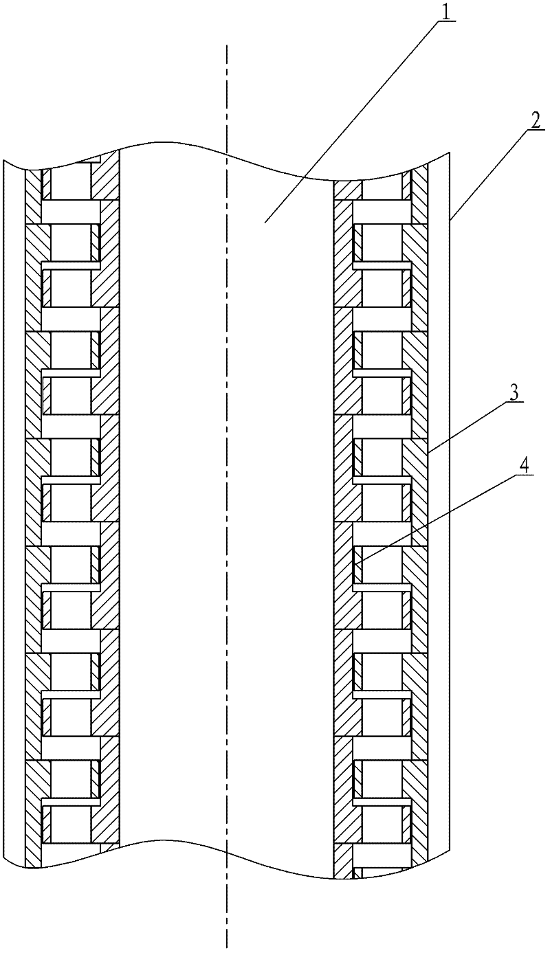
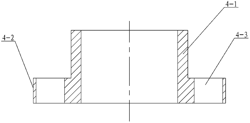
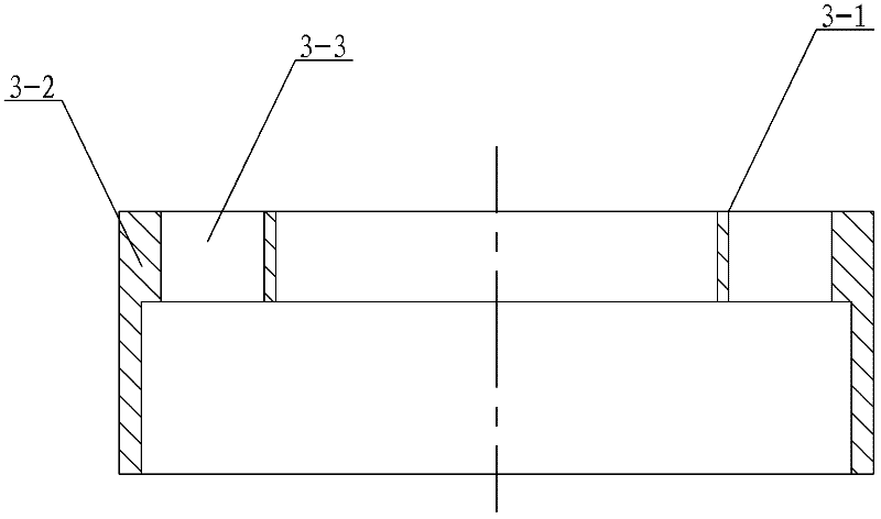
[0009] Specific implementation mode one: combine Figure 1-Figure 8 To illustrate this embodiment, the turbine stator and rotor assembly of this embodiment includes a shaft 1 and a housing 2, and the turbine stator and rotor assembly also includes a plurality of stator blade disks 3 and a plurality of rotor blade disks 4, each rotor blade disk 4 is provided with a stator blade disk 3, each rotor blade disk 4 and a stator blade disk 3 form a stage 5, the reaction degree of the stage 5 is less than 0.5, and multiple stages 5 are sequentially set on the shaft 1 from top to bottom, The end faces of multiple stages 5 are pressed and fitted, and the housing 2 is set on the outside of multiple stages 5. The stator blade disk 3 includes a cylindrical stator inner disk 3-1, a cylindrical stator outer disk Disk 3-2 and a plurality of stator blades 3-3, the cylindrical stator outer disk 3-2 is set on the cylindrical stator inner disk 3-1, and the plurality of stator blades 3-3 are evenly...
specific Embodiment approach 2
[0012] Specific implementation mode two: combination Figure 1-Figure 8 Describe this embodiment. In this embodiment, the stage pressure drop is 80-90kPa, the volume flow rate is 28-32L / s, and when the rotor speed is 700-1300rpm, the stage efficiency is 60-70%, and the power is 1.2-1.6kW. With such setting, according to the low-speed decompression characteristics of the stage, when the speed deviates from the design speed, the pressure drop of the stage will decrease, and the working state of the turbodrill can be judged according to the ground pressure, which is convenient for the drill staff to monitor and operate remotely. Other compositions and connections are the same as in the first embodiment.
specific Embodiment approach 3
[0013] Specific implementation mode three: combination Figure 1-Figure 8 Describe this embodiment. In this embodiment, the stage pressure drop is 85kPa, the volume flow rate is 30L / s, and the rotor speed is 1000rpm, the stage efficiency can reach 66%, and the power is 1.5kW. With such setting, according to the low-speed decompression characteristics of the stage, when the speed deviates from the design speed, the pressure drop of the stage will decrease, and the working state of the turbodrill can be judged according to the ground pressure, which is convenient for the drill staff to monitor and operate remotely. Other compositions and connections are the same as those in Embodiment 1 or Embodiment 2.
[0014] The working principle of turbodrill is as follows:
[0015] The drilling fluid from the high-pressure drilling pump on the ground enters the stator and rotor of the turbodrill through the drill pipe of the turbodrill, depressurizes and accelerates in the stator, flows i...
PUM
 Abstract
Description
Claims
Application Information
 - R&D
- Intellectual Property
- Life Sciences
- Materials
- Tech Scout
- Unparalleled Data Quality
- Higher Quality Content
- 60% Fewer Hallucinations
Browse by: Latest US Patents, China's latest patents, Technical Efficacy Thesaurus, Application Domain, Technology Topic, Popular Technical Reports.
© 2025 PatSnap. All rights reserved.Legal|Privacy policy|Modern Slavery Act Transparency Statement|Sitemap|About US| Contact US: help@patsnap.com