Power-off brake device

A technology of braking device and braking effect, applied in the direction of braking actuators, gear transmission mechanisms, brake types, etc., can solve problems such as difficult to use the rotary table, difficult to grasp the brake clearance, and the deflection of the brake table

Inactive Publication Date: 2012-05-16
IND TECH RES INST
View PDF10 Cites 3 Cited by
  • Summary
  • Abstract
  • Description
  • Claims
  • Application Information

AI Technical Summary

Problems solved by technology

[0004] For existing patents, such as US Patent Publication No. US20100175505 "CLAMPINGDEVICE FOR ROTARY INDEX DEVICE FOR MACHINE TOOL", the structure of this case is characterized by a curved pressure plate with elastic preload and a thin brake disc. The curved brake pressure plate is processed Preload to a certain height, so that it can press the disc under the condition of elastic deformation to achieve the purpose and function of braking. When the oil pressure enters the piston, the pressure plate will loosen the clamping force on the disc. The disadvantage of this case is that the bending pressure plate is not easy to process, it is difficult to adjust the assembly gap, it is difficult to replace it, and its braking force is not easy to control, it is difficult to position the moving brake, and it cannot be applied to large or high rotary table
[0005] Another example is the U.S. Patent US6457383 "ROTATING OR SWIVELING DEVICE OFA MACHINE TOOL". This case uses oil pressure to drive the workbench up and down and uses a slope to increase the braking force. The disadvantage of this case is that its structure is complicated, which makes it difficult to assemble or replace It cannot be applied to high-speed rotary tables, and because the braking structure of this case is not for power-off braking, it cannot brake when power is off
[0006] Another example is U.S. Patent US378672 "CLAMP FOR ROTARY TABLES", which uses a hydraulic device to drive a cam mechanism to open or clamp the jaws to achieve the purpose of braking. The disadvantage of this case is that it is difficult to simultaneously control the jaws to expand simultaneously , the brake displacement is large, the precision positioning brake function is weak, and the brake clearance is difficult to grasp, and the table will deflect when braking, which cannot be applied to the high-speed rotary table. Since the brake structure of this case is not for power-off braking, Therefore, it is not possible to brake when the power is cut off
[0007] Another example is the Chinese patent CN2835553Y "power-off braking device for oil drilling or wind power generation". In this case, when the power is cut off or the workbench is stopped, a spring device is used to clamp the relative brakes to clamp the plates to make the rotating object Stop, when restarting, the hydraulic cylinder will prop out to loosen the locking piece. Although the clamping torque of this case structure is high, the multiple of the braking element is larger than the rotating section. When installing, it is necessary to use a spreader, which is not easy to install, and also It is difficult to use on a general rotary table. In addition, the structure of this case cannot ensure that all the brake pads are clamped at the same time. The brake displacement is large, and the precise positioning brake function is weak.

Method used


Image

  • Power-off brake device
  • Power-off brake device
  • Power-off brake device

Examples


Embodiment Construction

[0057] The technical means and effects used by the present invention to achieve the purpose will be described below with reference to the accompanying drawings, and the embodiments listed in the following drawings are only for auxiliary explanation, so as to facilitate the understanding of the examiners, but the technical means of this case are not Not limited to the figures listed.

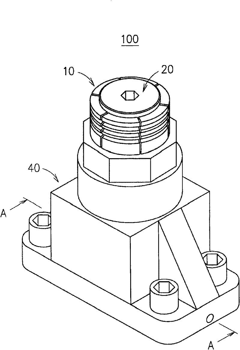
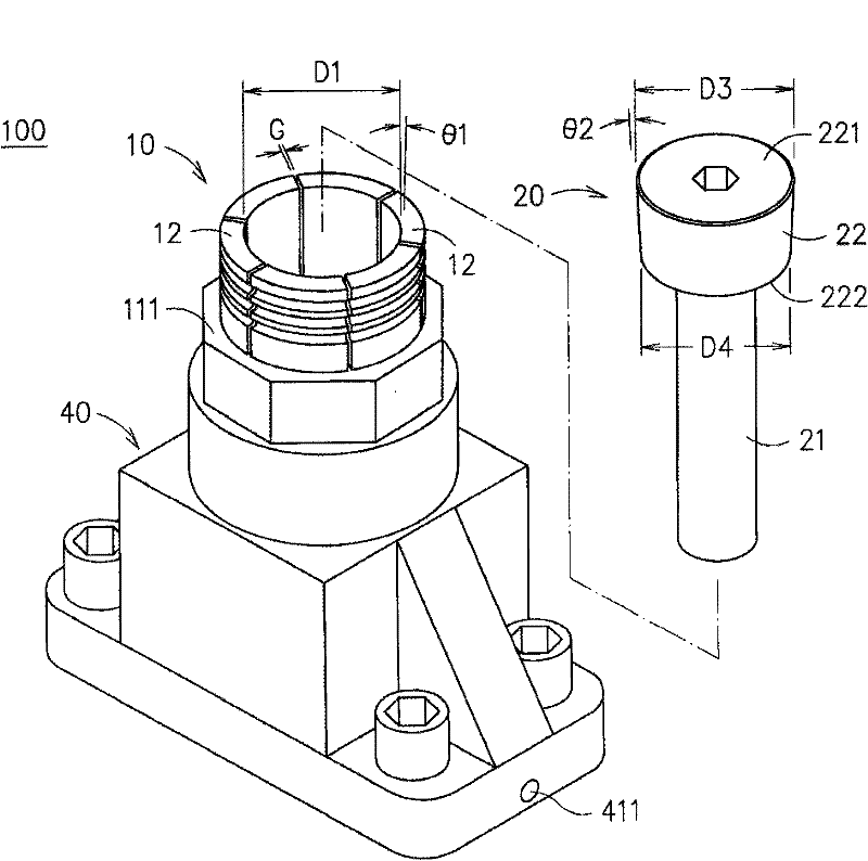
[0058] see Figure 1 to Figure 3 As shown, the power-off brake device 100 provided by the present invention includes an elastic claw element 10, a spindle 20 and a driving device 30, and the elastic claw element 10, the spindle 20 and the driving device 30 are arranged on a base 40 .

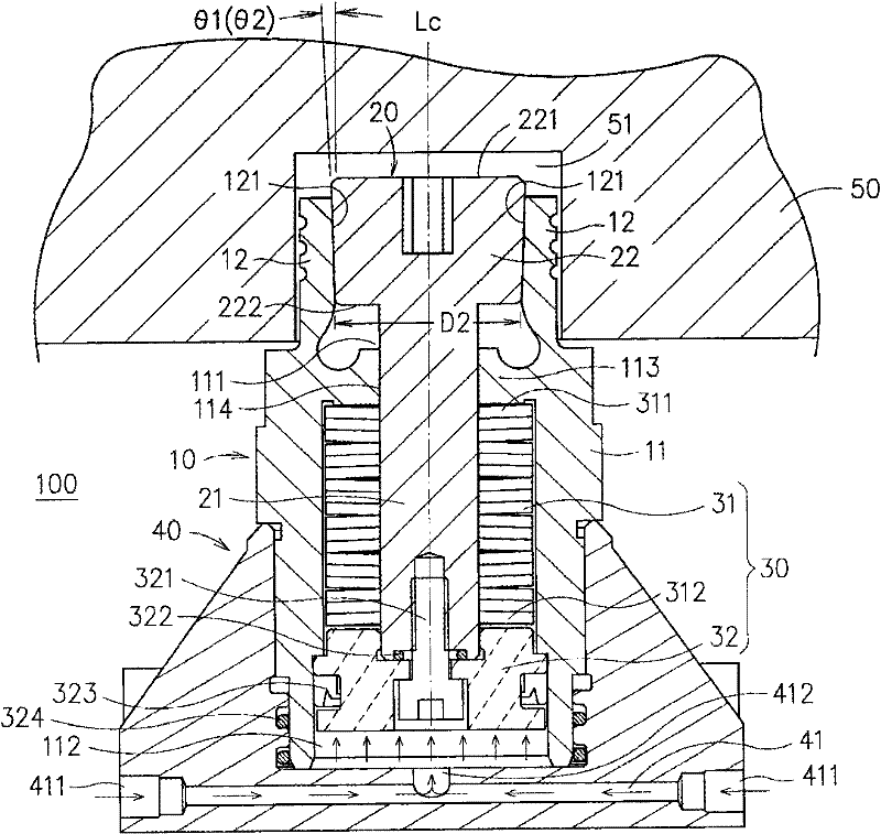
[0059]The elastic claw element 10 has a tubular main body 11, the tubular main body 11 has an axis Lc, and the tubular main body 11 has a first end 111 and a second end 112 opposite and communicating with each other along the axis Lc. The first end 111 of the tubular body 11 is provided with a partition 113, and ...


PUM


Abstract

The invention discloses a power-off brake device which comprises an elastic claw component, a core shaft and a driving device, wherein the elastic claw component is provided with a tubular main body, the tubular main body is provided with a first end and a second end along the axis of the tubular main body, the first end and the second end are opposite to each other and are communicated, a plurality of elastic claws are arranged at the first end of the tubular main body, the core shaft is composed of a shaft body and a conical head part, the shaft body is arranged in the tubular main body through a shaft, the conical head part is positioned in the plurality of encircling elastic claws, the driving device can drive the core shaft to move between a first position and a second position in a reciprocating manner, when the core shaft is positioned at the first position, the conical head part can release the elastic claws to make the outer lateral walls of the elastic claws and the inner lateral wall of a concave part of a rotary table separated, and when the core shaft is positioned at the second position, the conical head part can push the elastic claws to make the outer lateral walls of the elastic claws and the inner lateral wall of the concave part of the rotary table prop against each other.

Description

technical field [0001] The invention relates to a power-off braking device, in particular to a power-off protection device which uses oil pressure to drive elastic claws to open to achieve the purpose of braking. The braking force is stable and reliable, the structure is simple, the production cost is low, and the weight is light. It is small in size and easy to replace, especially suitable for large rotary modules, which can avoid industrial safety hazards caused by sudden power failures during the operation of large rotary modules. Background technique [0002] Generally, the so-called large-scale rotary module includes a rotary table that contains hydrostatic bearings and servo motors in machine tools and can perform large-scale turning and milling combined processing, as well as wind power generation equipment and oil drilling equipment. When a large rotating module rotates at high speed, due to the extremely high moment of inertia, a considerable degree of damage will o...

Claims


Application Information

Patent Timeline
Patent Type & Authority Applications(China)
IPC IPC(8): F16D63/00F16D65/18F16D121/04
Inventor 陈尚德廖建智陈志明张恩生
Owner IND TECH RES INST
Why Eureka
Try Eureka