Zero-position sensor

A zero-position sensor and device technology, applied in instruments, measuring devices, optical devices, etc., can solve the problems of deviation in the displacement measurement of the laser interferometer, affecting the accurate measurement of the laser interferometer, etc.

Active Publication Date: 2012-05-16
SHANGHAI MICRO ELECTRONICS EQUIP (GRP) CO LTD
View PDF4 Cites 6 Cited by
  • Summary
  • Abstract
  • Description
  • Claims
  • Application Information

AI Technical Summary

Problems solved by technology

Due to the inaccurate data information of the reference point, the displacement measurement of the laser i

Method used


Image

  • Zero-position sensor
  • Zero-position sensor
  • Zero-position sensor

Examples


Embodiment Construction

[0029] Below in conjunction with accompanying drawing, the present invention is described in further detail:

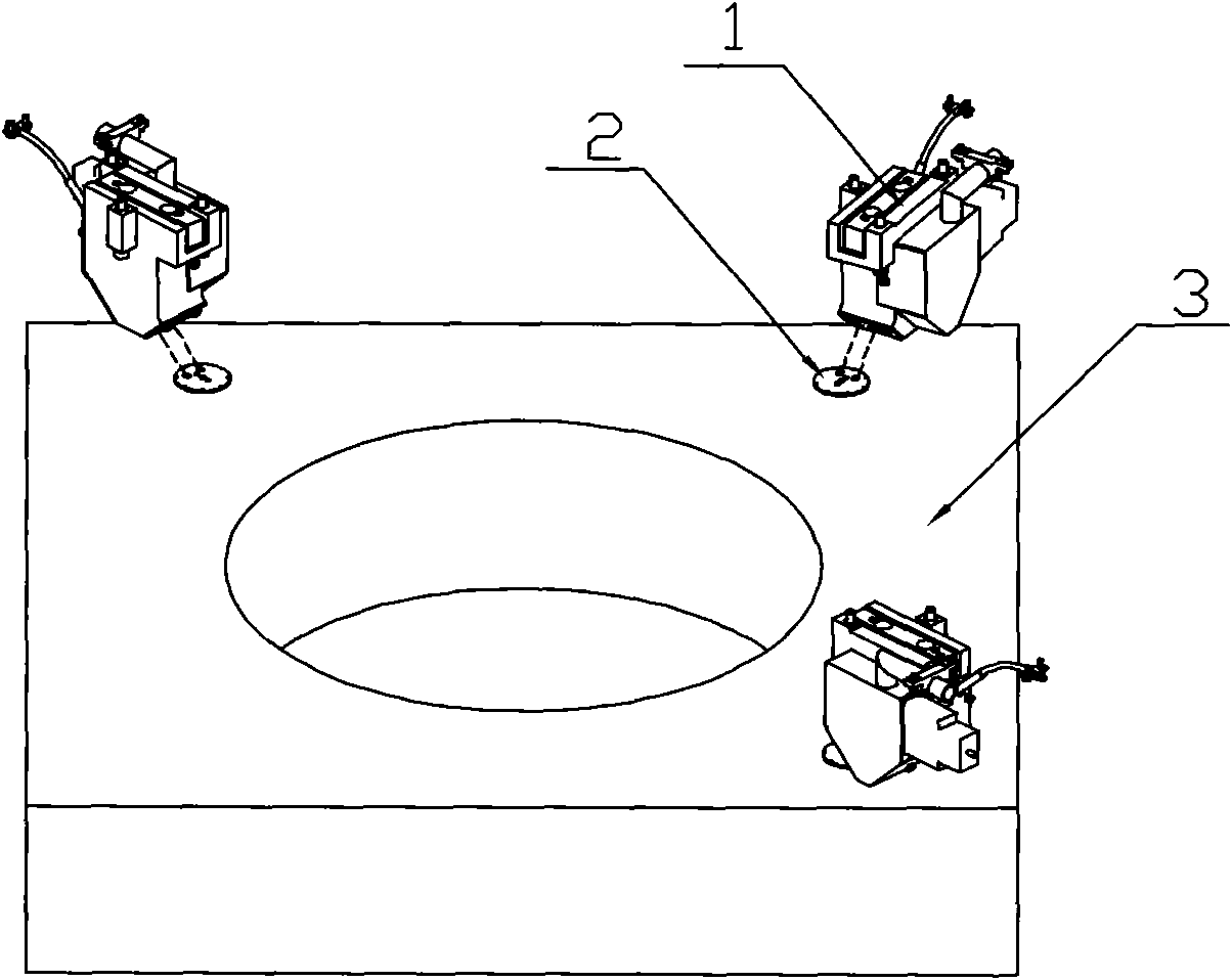
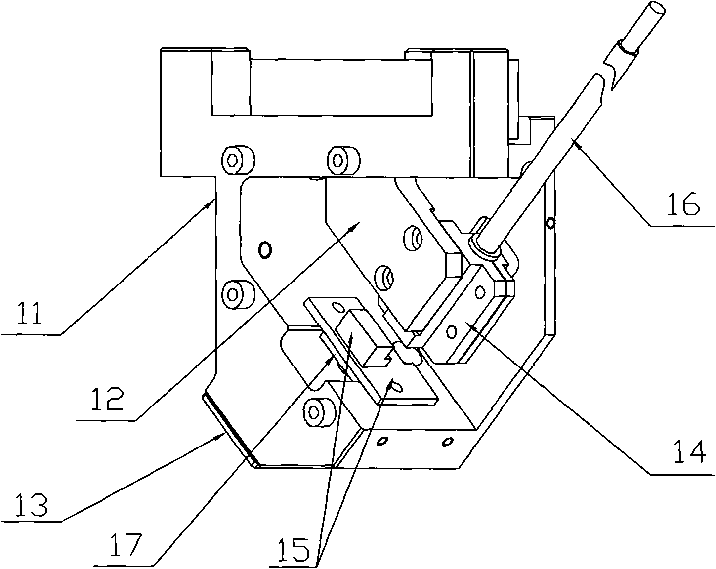
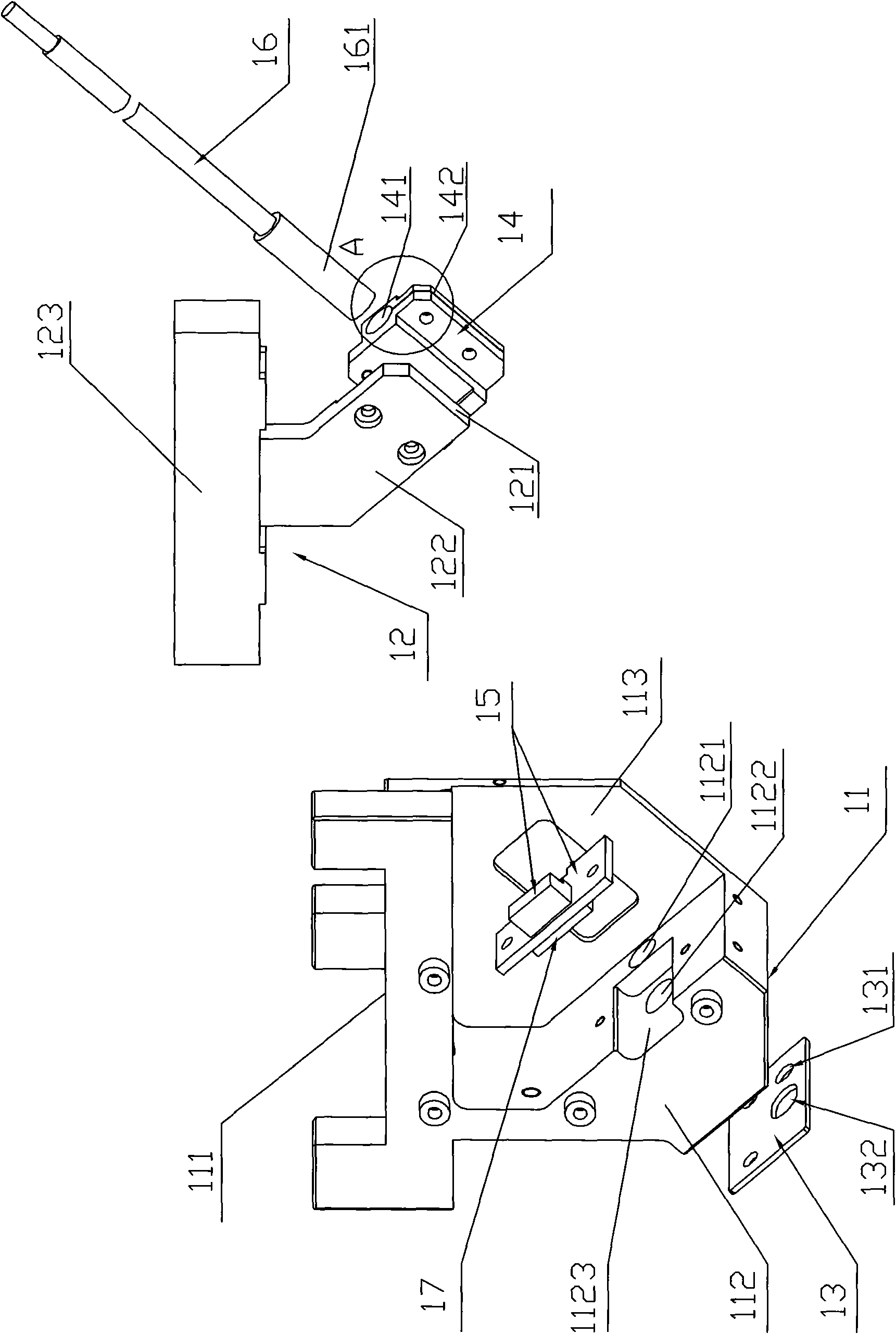
[0030] Such as Figure 1-11 As shown, the zero sensor of the present invention includes a host module 1, and the host module 1 includes a base 11, and the base 11 is provided with a laser collimating mirror 16 and a spot position detection device 17; the spot position The detection device 17 receives the parallel light beam reflected by the reflection module 2 installed on the workpiece table 3; the reflection module 2 parallel reflects the laser beam emitted by the laser collimator 16, and the spot position detection device 17 is electrically connected to A printed circuit board 15 that converts the sensed optical signal into an electrical signal.

[0031] Such as figure 2 , image 3 , Figure 5 , Image 6 , Figure 7 , Figure 8 As shown, the base 11 of the host module 1 includes a bottom plate 111 and a sloping plate 112, the bottom plate 111 is provided wi...


PUM


Abstract

The invention discloses a zero-position sensor, which comprises a host module (1). The host module (1) comprises a base (11). A laser collimating mirror (16) and a light spot position detecting device (17) are arranged on the base (11). The light spot position detecting device (17) is used for receiving parallel beam reflected by a reflective module (2) installed on a work-piece table (3). The reflective module (2) is used for reflecting laser beam emitted by the laser collimating mirror (16) in parallel. The light spot position detecting device (17) is electrically connected with a printed circuit board (15) for converting an inducted optical signal into an electrical signal. The zero-position sensor disclosed by the invention is applied to a position measurement system and has the advantage of being high in measurement precision.

Description

technical field [0001] The invention relates to a zero position sensor which provides an initial position for a laser interferometer of a position measurement system of an integrated circuit lithography machine. Background technique [0002] In the position measurement system of the integrated circuit lithography machine, the position measurement system of the workpiece table of the lithography machine relative to the base uses a laser interferometer. The laser interferometer is an incremental measurement system that can only provide accurate measurement of relative displacement. Therefore, before using the laser interferometer for position measurement, it is necessary to use a zero position sensor to provide an initial position for the laser interferometer, which is an absolute reference. Location. This absolute reference position is used as a reference point when using a laser interferometer for displacement measurement. In the prior art, a one-dimensional position senso...

Claims


Application Information

Patent Timeline
IPC IPC(8): G01B11/00G03F7/20
Inventor 王凯
Owner SHANGHAI MICRO ELECTRONICS EQUIP (GRP) CO LTD
Why Eureka
Try Eureka