Base station interaction method and device
A technology for base stations and interactive information, applied in data exchange networks, digital transmission systems, wireless network protocols, etc., can solve problems such as delays that cannot meet requirements
- Summary
- Abstract
- Description
- Claims
- Application Information
AI Technical Summary
Problems solved by technology
Method used
Image
Examples
Embodiment 1
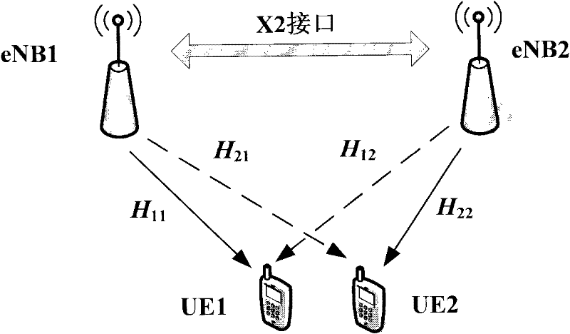
[0033] This example is based on the figure 2 Implementation scheme of CS / CB transmission mode under the downlink LTE-A system. The base station information interaction process is that UE1 will measure and obtain the channel matrix H 11 and H 12 Feedback to eNB1, eNB1 will H 12 Interact with eNB2; similarly, UE2 will measure the channel matrix H 21 and H 22 Feedback to eNB2, eNB2 will H 21 Interact with eNB1. eNB1 utilizes H 11 and H 21 Calculate the optimal precoding matrix W 1 , eNB2 utilizes H 22 and H 12 Calculate the optimal precoding matrix W 2 . eNB1 then sets W 1 Interact with eNB2, and eNB2 sends W 2 Interact with eNB1 for calculating their respective CQIs.
[0034] Figure 4It is a schematic diagram of the interactive system in this embodiment. Each interactive base station is added with a GE network port, and the network port is connected to the core network through a switch with a network cable.
[0035] Figure 5 is a schematic diagram of informa...
Embodiment 2
[0046] The interaction method of Embodiment 2 is exactly the same as that of Embodiment 1, but the physical connection method of the interactive system is different, as shown in the attached Figure 7 As shown, the data interaction of calling the Socket interface function proposed by the present invention for IP-based transmission is directly implemented on the physical interface of the X2 interface without additional GE network ports. That is, the direct interaction based on IP transmission proposed by the present invention and the existing X2 protocol-based interaction in LTE share the same physical interface.
[0047] In the scenario of non-cooperative transmission mode, when the handover of the connected UE in the LTE access system is performed in the same MME, the handover process does not involve the change of MME and S-GW.
[0048] In this interaction scenario, the interaction information required for switching can be interacted through the original X2 interface protoco...
Embodiment 3
[0051] Embodiment 3 is based on the attached figure 2 The implementation scheme of the CS / CB transmission mode of the downlink LTE-A system shown. The difference is that Embodiment 3 realizes the connection and interaction of adjacent base stations through the ATM (Asynchronous Transfer Mode, asynchronous transfer) interface, and the interface also includes a physical interface that can directly transmit based on the transport layer below, Figure 9 It is a schematic diagram of the interactive system of Embodiment 3, the adjacent base stations are connected to the ATM network through the ATM switch, and the interactive data is realized through the ATM network based on the data link layer.
[0052] Figure 10 It is an interactive flowchart of the channel matrix and the optimal precoding matrix in this embodiment, and the specific process includes the following steps:
[0053] Step A01: Each base station determines the interaction set according to the channel matrix fed back ...
PUM
 Abstract
Description
Claims
Application Information
 - R&D
- Intellectual Property
- Life Sciences
- Materials
- Tech Scout
- Unparalleled Data Quality
- Higher Quality Content
- 60% Fewer Hallucinations
Browse by: Latest US Patents, China's latest patents, Technical Efficacy Thesaurus, Application Domain, Technology Topic, Popular Technical Reports.
© 2025 PatSnap. All rights reserved.Legal|Privacy policy|Modern Slavery Act Transparency Statement|Sitemap|About US| Contact US: help@patsnap.com


