Supercharge Your Innovation With Domain-Expert AI Agents!

Gas leakage reduction system

A gas and air leakage technology, applied in the direction of flue gas combustion, indirect carbon dioxide emission reduction, steam boiler accessories, etc., can solve the problems of increasing the total pressure of flue gas and the difficulty of condensation in the gas treatment system

Active Publication Date: 2015-05-13
GENERAL ELECTRIC TECH GMBH
View PDF2 Cites 0 Cited by
  • Summary
  • Abstract
  • Description
  • Claims
  • Application Information

AI Technical Summary

Problems solved by technology

The partial pressure associated with the additional gas increases the total pressure of the flue gas, allowing CO 2 Condensation is more difficult, or even impossible

Method used


Image

  • Gas leakage reduction system
  • Gas leakage reduction system
  • Gas leakage reduction system

Examples


Embodiment Construction

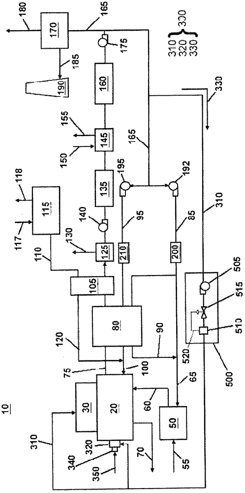
[0019] Disclosed herein is a system for a power plant, and more particularly, a system for significantly reducing and / or effectively minimizing air leakage (eg, air leaks) into a boiler of an oxy-fired power plant Gas leak reduction system. refer to figure 1 , the power plant 10 includes a furnace 20 . In the exemplary embodiment, furnace 20 is an oxy-fired boiler, but is not limited thereto. For example, furnace 20 may be a conventional boiler (not shown) or a CO 2 A capture preparation boiler (not shown), although the alternative exemplary embodiment is not limited thereto. For illustration purposes only, the following will figure 1 The oxy-fired boiler 20 shown in Power Plant 10 is discussed.

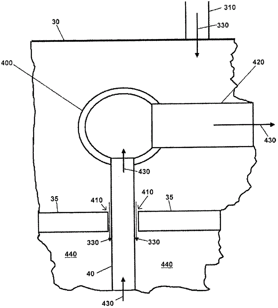
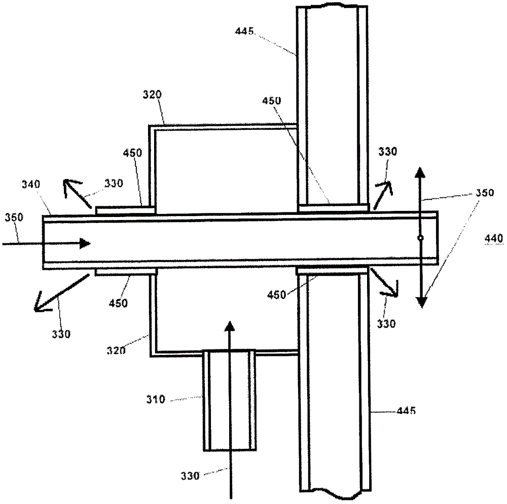
[0020] The power plant 10 according to the exemplary embodiment also includes a boiler roof 30 located above the oxy-fired boiler 20, such as figure 1 shown in . More specifically, the boiler roof 30 is positioned adjacent the boiler top tube panel 35 to receive the heat excha...


PUM


Abstract

An air infiltration abatement system (300) for a power plant (10) includes a recirculated flue gas source (175), a recirculated flue gas supply line (310) connected to the recirculated flue gas source (175) and a power plant component. The power plant component has a leakage area in fluid communication with the recirculated flue gas supply line (310). The recirculated flue gas source (175) receives a combustion flue gas (75) from an oxygen fired boiler (20) of the power plant (10), and provides the combustion flue gas (75) to the recirculated flue gas supply line (310). The recirculated flue gas supply line (310) supplies the combustion flue gas (75) as a recirculated flue gas (330) to the oxygen fired boiler (20) via the leakage area of the power plant component.

Description

technical field [0001] The present disclosure relates generally to oxy-fired boilers and, more particularly, to air leakage reduction systems for such boilers. Background technique [0002] There is growing concern about CO 2 Emissions of carbon dioxide and other greenhouse gases into the atmosphere are causing climate change and other as yet unknown consequences. Since existing power plants burning fossil fuels are the largest CO 2 One source of emissions, capturing CO from flue gases from these devices 2 has been seen as reducing atmospheric CO 2 important means of emissions. To this end, oxy-combustion is a promising boiler technology developed for capturing CO from flue gases of both existing power plants and new power plants. 2 . [0003] In an oxy-fired power plant, a fossil fuel (eg, such as coal) is burned during combustion in the power plant furnace in a similar manner as in eg an air-fired conventional power plant. However, in oxy-combustion power plants, ox...

Claims


Application Information

Patent Timeline
Patent Type & Authority Patents(China)
IPC IPC(8): F23C9/08F23C9/00F22B37/36
CPCF22B1/1884F22B37/42F23C9/00F23C2202/00Y02E20/34F23C9/08F22B37/36
Inventor G·N·利尔耶达尔N·Y·恩萨卡拉M·帕尔克斯G·D·朱科拉
Owner GENERAL ELECTRIC TECH GMBH
Features
  • R&D
  • Intellectual Property
  • Life Sciences
  • Materials
  • Tech Scout
  • Unparalleled Data Quality
  • Higher Quality Content
  • 60% Fewer Hallucinations
Learn More