
Instrument connection type unit pack combined cell cartridge

A technology of battery cells and cell groups, applied in the direction of secondary batteries, battery pack components, circuits, etc., can solve the problems of inability to increase the current capacity of battery cells, ineffective use of cable space, and inability to exceed current capacity, etc. , to achieve the effect of solving low stability, eliminating current/voltage imbalance, and minimizing contact resistance

Inactive Publication Date: 2012-05-16
MEGABESS +1
View PDF3 Cites 11 Cited by
  • Summary
  • Abstract
  • Description
  • Claims
  • Application Information

AI Technical Summary

Problems solved by technology

[0011] In addition, in the case of expanding the battery cell group as described above, cables are required when connecting the battery cell group, so there are problems such as complexity due to cables, ineffective use of space due to space occupied by cables, and narrow space.
[0012] In addition, in the way of welding the terminals of the battery cells on the connection boards electrically connected to the battery cells, a lot of heat is generated (especially during discharge) due to the small contact area (welding point area) with the connection boards, which has great impact on stability. unfavorable
[0013] In addition, in the structure in which the terminal of the battery cell and the connection plate are connected at the welding point, the contact area is small, so there is a limitation in the current capacity that cannot increase the current capacity of the battery cell, etc.
It is impossible to enlarge the soldering point as a contact point for soldering, so the current capacity cannot be exceeded

Method used


Image

  • Instrument connection type unit pack combined cell cartridge
  • Instrument connection type unit pack combined cell cartridge
  • Instrument connection type unit pack combined cell cartridge

Examples


Embodiment Construction

[0043] Hereinafter, preferred embodiments of the present invention will be described in detail with reference to the accompanying drawings.

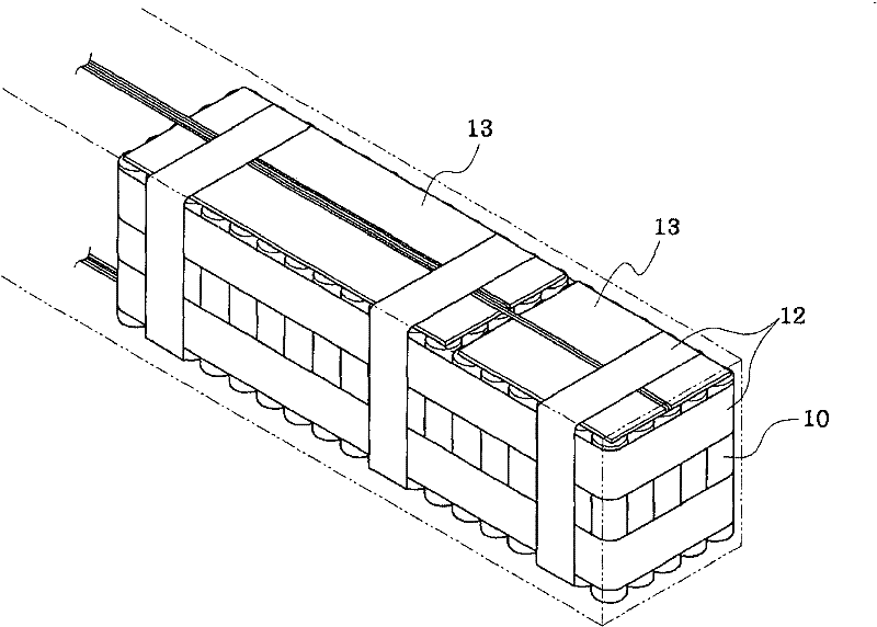
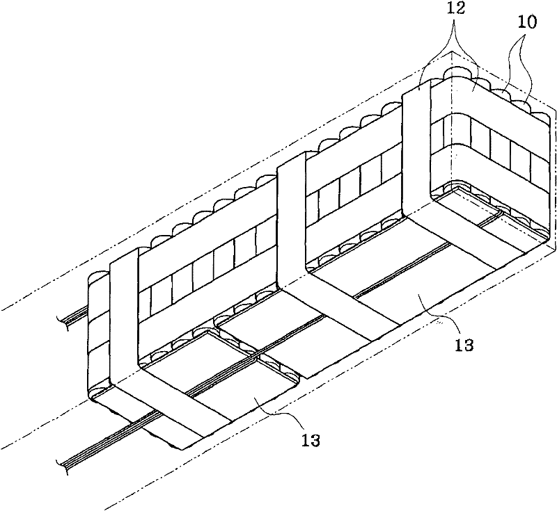
[0044] The unit pack combination type battery cell case of the present invention is characterized in that after connecting a plurality of battery cells (cells) using a tool (bus line) to form a unit pack (unit pack), the plurality of unit packs are assembled using a tool (intermediate conductor). Boards) are connected to form, and there are no cables and connectors in the unit group combination type battery unit case, and the entire unit group is formed and connected only by tools.

[0045] The cell pack combination type battery cell case of the present invention connects the battery cell and the cell pack using tools that are easy to connect and detach, so assembly performance and productivity are greatly improved, and (in the power storage device of the present invention) adjustment and change are possible. The current and voltage capa...


PUM


Abstract

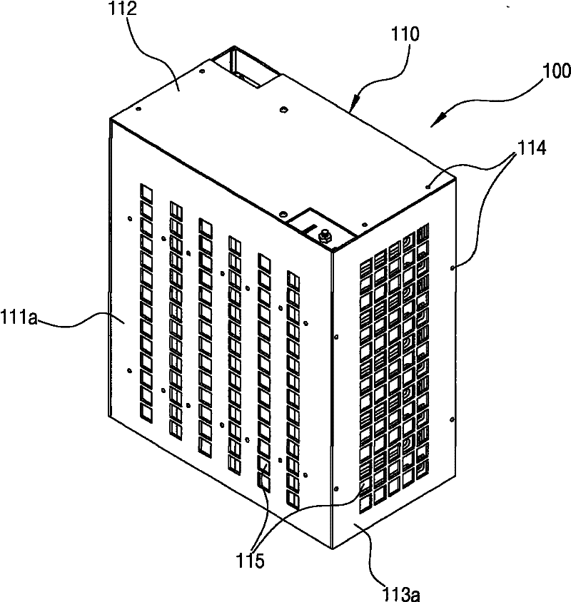
The present invention relates to an instrument connection type unit pack combined cell cartridge assembled into a compound cell interconnection mesh, and to a combined cartridge electricity storage device assembled into a compound unit interconnection mesh in which a plurality of cell cartridges are electrically interconnected. The unit pack combined cell cartridge of the present invention is configured such that a plurality of cells are interconnected into a unit pack using a suitable device (bus bar), and a plurality of unit packs are interconnected into a unitary cartridge using a suitable device (intermediate conductor plate).The combined cartridge electricity storage device of the present invention is configured such that a plurality of unit pack combined cartridges are accommodated in an outer case and interconnected into a serial or parallel compound interconnection structure to form a unitary system. The present invention interconnects cells, unit packs and cartridges using an easily connectible or separable instrument, to thereby allow for ease of assembly and improve productivity. In addition, the number of cells used in a unit pack, the number of unit packs used in a cartridge, and the number of cartridges used in an electricity storage device can be adjusted and changed to change current capacity and voltage capacity with ease.

Description

technical field [0001] The present invention relates to a battery cell case, and more particularly to a battery cell case that is modularized by assembling a plurality of unit cells (cells) in a case. Background technique [0002] As an example of a storage battery (secondary battery) that stores electrical energy and supplies it to a load that requires it, when looking at the structure of a conventional lithium-ion cell pack (Lithium-ion cell pack), the required capacity is manufactured through the following process Battery cell pack: First, a unit pack is made by bundling a plurality of lithium-ion battery cells (cells) capable of charging and discharging, then a large pack is remade by combining multiple unit packs, and a larger pack is made by combining them again. [0003] In this case, conventionally, a unit battery cell with a circular cross section (cylindrical battery cell) or a unit battery cell with a square cross section is bundled with a material such as a glass...

Claims


Application Information

Patent Timeline
Patent Type & Authority Applications(China)
IPC IPC(8): H01M10/00H01M50/204H01M50/262H01M50/284H01M50/296H01M50/505H01M50/509H01M50/512
CPCY02E60/12H01M10/5018H01M10/5004H01M2/206H01M10/5032H01M10/503H01M2/202H01M10/5065H01M2/1077H01M10/647H01M10/643H01M10/627H01M10/613H01M10/6562Y02E60/10H01M50/204H01M50/284H01M50/509H01M50/512H01M50/296H01M50/505H01M50/262H01M10/00
Inventor 姜晶郁李赞基张龙虎金夏岭
Owner MEGABESS
Learn More