Drill

A drill bit and vertical technology, applied in twist drills, drill accessories, drilling/drilling equipment, etc., can solve the problems of high cost and increased cost, and achieve the effects of low cost, stable edge, and long drill life

Inactive Publication Date: 2012-05-23
MAPAL FABRIK FUER PRAEZISIONSWERKZEUGE (DE)
View PDF10 Cites 2 Cited by
  • Summary
  • Abstract
  • Description
  • Claims
  • Application Information

AI Technical Summary

Problems solved by technology

Its disadvantage is that the drilling effect does not meet the requirements regarding the surface quality of the hole wall and the accuracy of the drilled hole shape in all cases, so it needs to be improved accordingly
In addition, the cost of manufacturing such drills is relatively high, thus increasing the cost

Method used


Image

  • Drill
  • Drill
  • Drill

Examples


Embodiment Construction

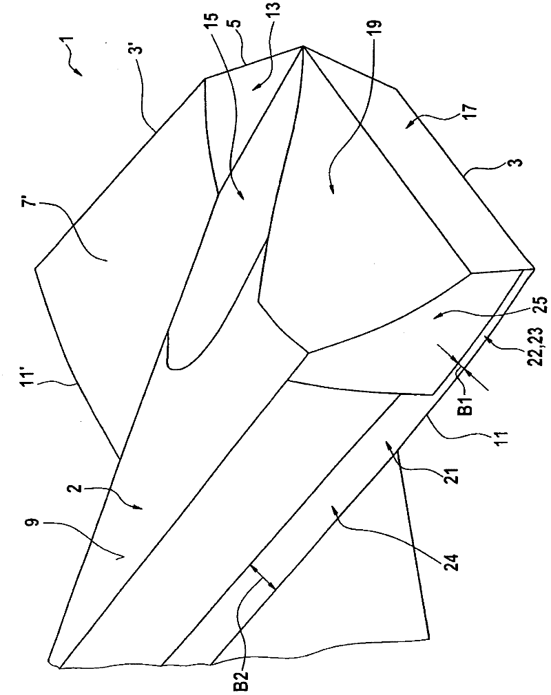
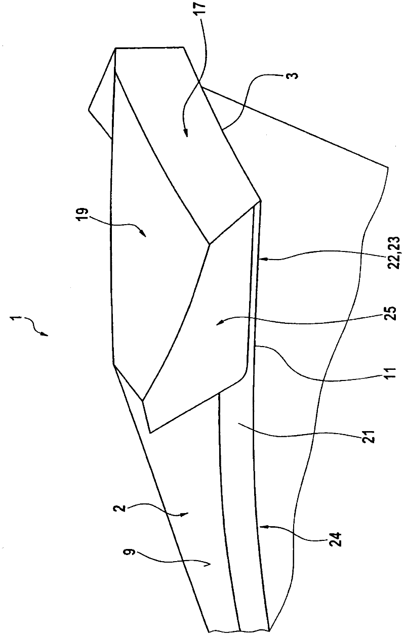
[0028] exist figure 1 A part of the drill bit 1 in the first embodiment is shown in a perspective view. Its viewing direction is the direction obliquely forward above the apex of the drill bit 1 .

[0029]In the exemplary embodiment shown here, the drill 1 is designed as an auger drill with a base body 2 on which a first main cutting edge 3 and a second main cutting edge arranged point-symmetrically with respect to the central axis of the drill 1 are provided. Edge 3'. In this exemplary embodiment, the two main cutting edges 3 , 3 ′ are preferably connected to each other by a chisel edge 5 extending through the central axis. The two main cutting edges 3 , 3 ′ are preferably arranged parallel to a diameter line running through the central axis, as seen in the direction of the end face of the drill 1 . These main cutting edges have an angle with respect to each other, commonly referred to as the apex angle, which is less than 90°. Therefore, the bit end with the main cutting...


PUM

PropertyMeasurementUnit
widthaaaaaaaaaa
widthaaaaaaaaaa
lengthaaaaaaaaaa

Abstract

A drill (1) for producing a drilled hole in workpieces comprising fibre-reinforced plastic is proposed, with at least one main cutting edge (3) on the end face, with at least one secondary cutting edge (11), provided in the region of a circumferential surface (9) of the drill (1), and with circularly ground lands (21), circumferentially adjoining the at least one secondary cutting edge (11, 11'). The drill is distinguished by the fact that the preferably continuous circularly ground lands (21) have, starting from a front region of the drill (1), a first longitudinal portion (22) with a first width (B1) and, adjoining thereto, a second longitudinal portion (24) with a second width (B2), wherein the width (B1) of the first longitudinal portion (22) is less, preferably less by a multiple, than the width (B2) of the second longitudinal portion (24).

Description

technical field [0001] The invention relates to a drill according to the preamble of claim 1 for producing boreholes in workpieces comprising fiber-reinforced composite materials. Background technique [0002] When processing materials with fiber-reinforced composites, such as glass-fiber-reinforced composites or carbon-fiber-reinforced composites, it is necessary, inter alia, that the fibers be cut cleanly on the cut edge without being torn off from the material connection. If it is not clean, that is to say if the worn edge has protruding fibers, it will be more expensive and thus result in higher reprocessing costs or even scrap the processed workpiece. When drilling such materials, especially at the exit of the drill hole, that is, at the position where the drill bit penetrates the workpiece, there will be worn edges, the so-called delamination (Delamination), which occurs, for example, in aircraft construction. Drilling rivet holes in components can be very problematic...

Claims


Application Information

Patent Timeline
Patent Type & Authority Applications(China)
IPC IPC(8): B23B51/02
CPCB23B51/02B23B2251/446B23B2260/132B23B2251/48B23B2226/27Y10T408/909
Inventor 迪特·克雷斯
Owner MAPAL FABRIK FUER PRAEZISIONSWERKZEUGE (DE)
Why Eureka
Try Eureka