

Compound mill
A rolling and compound technology, which is applied in the field of compound rolling machines, can solve the problems of iron filings, waste of materials, and low work efficiency, and achieve the effects of improving production efficiency, reducing labor intensity, and realizing automation
- Summary
- Abstract
- Description
- Claims
- Application Information
AI Technical Summary
Problems solved by technology
Method used
Image

Examples
Embodiment Construction
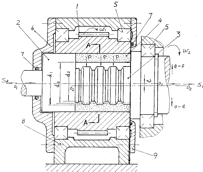
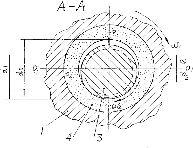
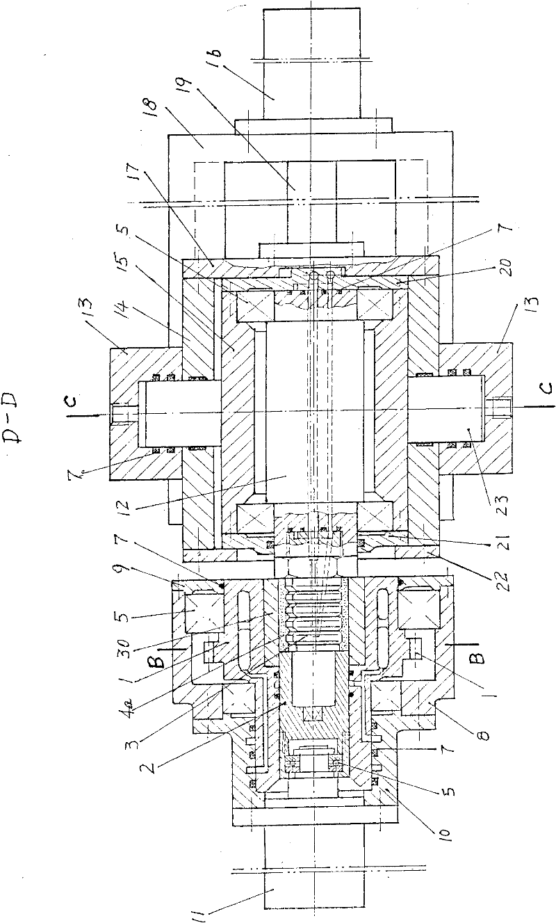
[0028] exist figure 1 Among them, a roller (1) is positioned with a bearing (5), and the interior is a cylindrical space, one end of which is closed by a movable stopper (2), and the other end is first loaded into a section of tubular blank (4), and then extended into a A roller shaft (3) with an annular groove; the roller (1), the head (2) and the roller shaft (3) constitute a mould, driven by an external force, the inner wall of the blank (4) is simultaneously enlarged and The reduced-diameter compound roller is extruded to make it a qualified workpiece with a cylindrical surface on the outside and an annular groove on the inside. See image 3 Workpiece (4a) in .
[0029] exist Figure 4 , there is a ring gear on the outside of the roller (1) meshing with the pinion (31), see Figure 4 , when the motor (not shown) drives the pinion (31) through the winding transmission part (34), the roller (1) realizes the uniform rotation with an angular velocity of 1.
[0030] exist ...
PUM
 Abstract
Description
Claims
Application Information