Rotary cutter sharpening seat for cutter

A tool sharpening seat and cutting tool technology, which is applied in lathe tools, planer/slotting machine tools, manufacturing tools, etc. It can solve the problem that the miniaturization and economy of tool grinding machines are difficult to achieve, and the overall structural rigidity of the tool grinding seat Insufficient, limited scope of application of tool grinding machines, etc., to achieve the effect of improving sharpening efficiency and convenience, improving rigidity, and good locking performance

Active Publication Date: 2012-05-30
JIAXING EXPERT MACHINE TECHN
View PDF5 Cites 12 Cited by
  • Summary
  • Abstract
  • Description
  • Claims
  • Application Information

AI Technical Summary

Problems solved by technology

Thereby reducing sharpening efficiency and accuracy, limiting the scope of application of the tool grinder, and the miniaturization and economy of the tool grinder are also difficult to achieve
There is contact rigidity between the rotating shaft of the third rotating part and the bushing, and the rotating part will deform and deviate when the cutter head is sharpened. This shift is amplified by the distance between the rotating shaft and the cutter head. Rigidity, so that the overall structure of the sharpening seat is not rigid enough, and the sharpening phenomenon of the grinder is serious, which reduces the sharpening accuracy of the turning tool
Its locking point is on the rotating shaft of the rotating part, while the sharpening force point is at the outermost end of the sharpening seat. The distance between the rotating shaft and the outer end tool is used as a lever for the sharpening force, which can easily overcome the rotating shaft lock. The locking force of the tight point causes the loosening of the rotating parts, which reduces the sharpening accuracy of the turning tool
[0004] U.S. Patent No. 4259814 Tool sharpening machine tool sharpening machine also discloses another structure in which the two rotating axes perpendicular to each other are used to set the angle of the common car blade and grind it, but it often changes the surface during sharpening. Movement depends on the uncertainty of the reference plane, and the machining accuracy is lower

Method used


Image

  • Rotary cutter sharpening seat for cutter
  • Rotary cutter sharpening seat for cutter
  • Rotary cutter sharpening seat for cutter

Examples


Embodiment Construction

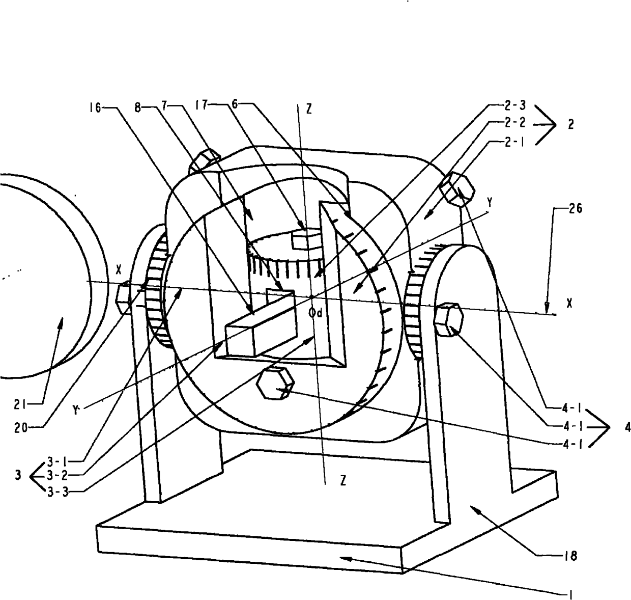
[0032] figure 2 It is the implementation structure diagram of the technical solution of the present invention, the Z rotating part 2-3 is in the middle of the mechanism, the turning tool 16 is installed in the turning tool installation hole 8 and is pressed by the screw 17, and the Z rotating part 2-3 is set on the Y rotating part 2-2Y Z In the middle hole 7, the Z rotating part 2-3 itself is the rotating shaft, and its Z rotating shaft 3-3 line is in line with the Y Z The center lines of the median hole 7 are collinear, and the turning tool 16 is perpendicular to the Z rotating shaft 3-3. due to Y Z Since the position hole 7 is arranged on the Y rotating member 2-2 and is perpendicular to the Y rotating shaft 3-2, the Z rotating shaft 3-3 of the Z rotating member 2-3 is also perpendicular to the Y rotating shaft 3-2. The Y rotating part 2-2 is set on the X of the X rotating part 2-1 Y In the center hole 6, the Y rotating part 2-2 itself is the rotating shaft, and its Y r...


PUM


Abstract

The invention discloses a rotary cutter sharpening seat for a cutter, comprising a base, rotating pieces, a rotary shaft and a locking piece, wherein the rotary shaft is divided into X, Y and Z rotary shafts; the Z rotating piece is provided with a lathe tool mounting hole, the center line of which is vertical to the Z rotary shaft of the Z rotating piece; the Y rotating piece is provided with a YZ middle-position hole, the center line of which is vertical to the Y rotary shaft of the Y rotating piece; the Z rotating piece is sleeved in the YZ middle-position hole, the center line of which is collinear with the axis of the Z rotary shaft; the X rotating piece is provided with an XY middle-position hole the center line of which is vertical to the X rotary shaft of the X rotating piece; the Y rotating piece is sleeved in the XY middle-position hole the center line of which is collinear with the axis of the Y rotary shaft; the center line of the YZ middle-position hole of the Y rotating piece is crossed on the X rotating piece; the base is also provided with an X rotating support; and the X rotating piece is sleeved on the X rotating support, the rotating shaft of which is collinear with the X rotary shaft of the X rotating piece. When the rotary cutter sharpening seat is used, after a tool grinding machine provided with the cutter sharpening seat is clamped and lathed, continuous multi-face grinding can be performed at any blade surface angles to finish integral lathing and blade sharpening once, the operation of clamping for multiple times is avoided, and angle space conversion is not needed; the big lathing offset when the angle is regulated is eliminated; the rigidity of the cutter sharpening seat is improved; machining errors due to the cutter relieving phenomenon are reduced; and the locking reliability is further improved to increase the convenience in use and realize the miniaturization of a matched tool grinding machine and higher blade grinding precision.

Description

technical field [0001] The invention relates to a tool clamping device of a tool grinder, in particular to a sharpening seat capable of grinding the blade after the tool rotation angle is positioned. Background technique [0002] Metalworking tools such as turning tools have edges formed by a plurality of facets at defined angles. The flank of the main cutting edge is defined by the main relief angle α o and the leading angle x r Orientation, the flank of the auxiliary cutting edge is determined by the auxiliary main relief angle α o ’ and vice leading angle x r ’ Orientation. See, the second edition of "Metal Cutting Handbook", edited by Shanghai Metal Cutting Technology Association, Shanghai Science and Technology Press, April 1984, pp. 4.19-4.21 of the first edition. [0003] Chinese Patent No. 200820086570.7 is a tool grinder, which discloses a tool grinder. The worktable of the tool grinder is equipped with a sharpening seat. The sharpening seat is used for clampin...

Claims


Application Information

Patent Timeline
Patent Type & Authority Applications(China)
IPC IPC(8): B24B3/00B24B3/34
Inventor 吕建清时晓云韩慧国
Owner JIAXING EXPERT MACHINE TECHN
Why Eureka
Try Eureka