Planar articulated robot arm mechanism

A robot arm, plane multi-joint technology, applied in manipulators, claw arms, manufacturing tools, etc., can solve problems such as stiffness reduction, improve reliability, meet the effect of simple structure, flexible and reliable movement

Active Publication Date: 2012-05-30
SHENYANG SIASUN ROBOT & AUTOMATION
View PDF11 Cites 15 Cited by
  • Summary
  • Abstract
  • Description
  • Claims
  • Application Information

AI Technical Summary

Problems solved by technology

In order to avoid movement interference, the common drive link and auxiliary link can only be installed above the upper arm of the SCARA arm. To save space, it is usually required that the thickness of the common drive link and auxiliary link should not exceed the thickness of the forearm, resulting in reduced stiffness

Method used


Image

  • Planar articulated robot arm mechanism
  • Planar articulated robot arm mechanism
  • Planar articulated robot arm mechanism

Examples


Embodiment 1

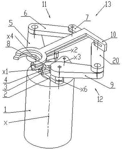
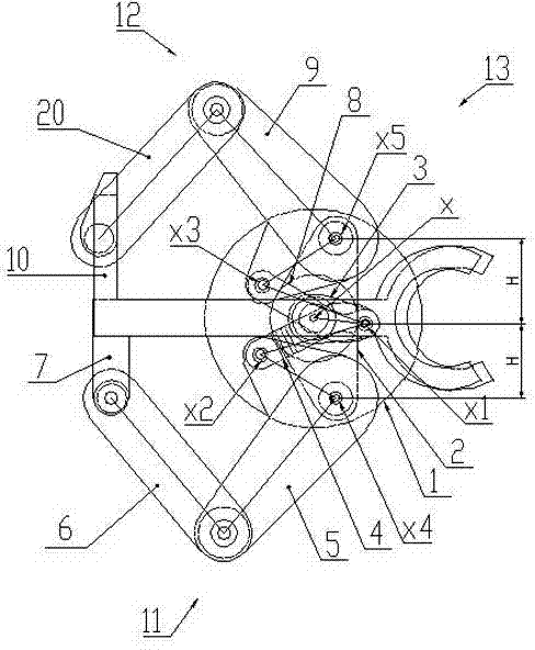
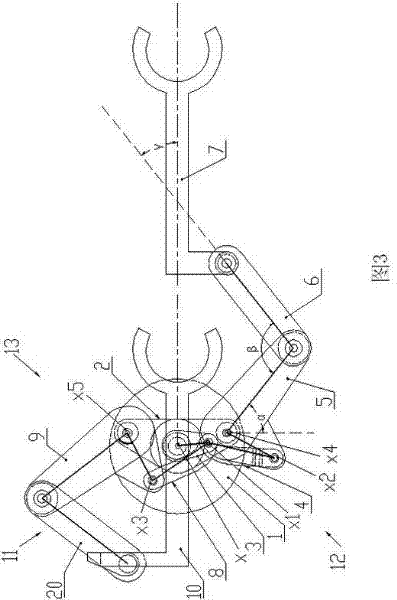
[0023] Example 1: Such as Figure 1-Figure 4 As shown, this example includes a drive unit 1, a base platform 2 and a double telescopic arm assembly 13. The drive unit 1 has two rotating shafts that are nested with each other-a rotating shaft inner shaft 27 and a rotating shaft outer shaft 26. The base platform 2 of the rotating shaft is connected to the lifting mechanism of the drive unit 1, and the dual telescopic arm assembly 13 is symmetrically installed on the base platform 2 with respect to the rotation axis x of the drive unit 1 through the fourth and fifth rotating joints x4, x5 On the outer shaft 26 of the rotary shaft, the inner shaft 27 of the rotary shaft is fixed to the common driving link 3 of the double telescopic arm assembly 13, and the lifting shaft 24, the outer shaft 26 of the rotary shaft and the inner shaft 27 of the rotary shaft respectively pass The independent motors are connected to the controller of the drive unit 1.

[0024] Such as figure 2 , image 3...

Embodiment 2

[0033] Example 2: Such as Figure 5 As shown, the overall structure of this example is the same as that of Embodiment 1, except that the third motor 16 of the inner shaft 27 of the rotating shaft in this example is mounted on the outer shaft 26 of the rotating shaft, and the two pulleys of the synchronous belt transmission mechanism They are respectively connected to the outer shaft 26 of the rotating shaft and the third motor 16. In this way, the outer shaft 26 of the rotating shaft and the inner shaft 27 of the rotating shaft are no longer independently driven. When the inner shaft 27 of the rotating shaft remains stationary and the outer shaft 26 of the rotating shaft rotates, the dual SCARA arm assembly makes an overall rotary movement; regardless of the outer shaft 26 of the rotating shaft For any movement, when the inner shaft 27 of the rotating shaft moves, the double SCARA arm components all make a telescopic movement.

Embodiment 3

[0034] Example 3: Such as Image 6 As shown, the difference between this embodiment and Embodiment 1 is: the drive unit 1 of this example has a rotating shaft—the inner shaft 27 of the rotating shaft. The base platform 2 with the built-in inner shaft 27 of the rotating shaft is connected to the lifting mechanism of the drive unit 1. Above, the double telescopic arm assembly 13 is installed on the base platform 2 symmetrically with respect to the rotation axis x of the drive unit 1 through the fourth and fifth rotary joints X4 and X5, namely: the first and second telescopic arm assemblies 13 The first pulley 17 in the boom 5, 9 is fixed on the base platform 2, and the inner shaft 27 of the rotating shaft is hinged with the first and second booms 5, 9 of the double telescopic arm assembly 13 through the common drive link 3 The lifting shaft 24 and the inner shaft 27 of the rotating shaft of the lifting mechanism are connected to the controller 28 of the driving unit 1 through the ...


PUM


Abstract

A planar articulated robot arm mechanism belongs to the technical field of an industrial robot. The planar articulated robot arm mechanism comprises a drive unit, a base platform and a double-telescopic arm assembly, wherein the drive unit is provided with at least one rotating shaft, i.e. a rotating shaft inner shaft, the base platform in which the rotating shaft inner shaft is arranged is connected with a lifting mechanism of the drive unit, the double-telescopic arm assembly is respectively and symmetrically arranged on the base platform through rotary joints relative to the rotary axis of the drive unit, the rotating shaft inner shaft is fixedly connected with a public drive connecting rod of the double-telescopic arm assembly, and a lifting shaft of the lifting mechanism and the rotating shaft inner shaft are respectively connected with a controller of the drive unit through a motor. According to the planar articulated robot arm mechanism, since a seven-parallel-rod mechanism is adopted, the rotating action of a double SCARA (selective compliance assembly robot arm) double-arm assembly can be realized, and the telescopic action can also be realized; and with the lifting mechanism in the drive unit, the lifting motion of the double SCARA double-arm assembly can be realized. The planar articulated robot arm mechanism is simple and compact in structure, is high in structural rigidity, is flexible and reliable in motion, is high in position precision and is high in reliability.

Description

technical field [0001] The invention belongs to the technical field of industrial robots, in particular to a planar multi-joint robot arm mechanism. Background technique [0002] With the continuous development of industries such as electronics, aerospace, military and biomedicine, modern industrial products and modern scientific experiment activities require miniaturization, precision, high purity, high quality and high reliability, and semiconductor components are required to be kept at a relatively high level of cleanliness. processing in low temperature environment. [0003] Small robots used for handling semiconductor devices must be able to adapt to high cleanliness and narrow space use environments, and at the same time meet the requirements of simple and compact structure, high structural rigidity, flexible and reliable movement, high repeat positioning accuracy and high reliability. [0004] In order to improve work efficiency, two sets of robotic arms are usually ...

Claims


Application Information

Patent Timeline
Patent Type & Authority Applications(China)
IPC IPC(8): B25J18/00
Inventor 曲道奎王凤利王金涛李学威
Owner SHENYANG SIASUN ROBOT & AUTOMATION
Why Eureka
Try Eureka