Eureka AIR delivers breakthrough ideas for toughest innovation challenges, trusted by R&D personnel around the world.

Bridge pushing construction method

A technology of jacking construction and construction method, which is applied in the direction of bridges, bridge construction, erection/assembly of bridges, etc. It can solve the problems of weakened bottom plate openings, large material consumption, and large internal force of bridges, etc., and achieves rapid construction, material saving, and The effect of expanding the range of use

Active Publication Date: 2012-05-30
SHANGHAI MUNICIPAL ENG DESIGN INST GRP
View PDF6 Cites 21 Cited by
  • Summary
  • Abstract
  • Description
  • Claims
  • Application Information

AI Technical Summary

Problems solved by technology

[0003] When the bridge is a straight line or a circular curve with the same radius, the temporary pier top support coincides with the bottom curve of the beam during the jacking process, which can be considered as an ideal contact; During the process, the top support of each temporary pier does not coincide with the curve of the bottom of the beam, and the contact condition changes with the relative position between the beam body and the temporary pier, which will cause some temporary pier to be empty or the reaction force is too large, which will cause excessive internal force of the bridge. Big, unfavorable to the safety of jacking construction
[0004] For this reason, wedge-shaped pads are usually installed at the bottom of the beam to fill up the bottom of the beam, and then the conventional jacking method is used for construction; but this method has disadvantages such as large material consumption, cumbersome construction process, and too many holes in the bottom plate to weaken the structure

Method used


Image

  • Bridge pushing construction method
  • Bridge pushing construction method
  • Bridge pushing construction method

Examples


Embodiment Construction

[0014] A bridge jacking construction method, characterized in that a support is provided on a temporary pier, and the elevation of the support of the temporary pier is adjusted in the gap between bridge girder sections, so that the bottom of the bridge girder is effectively in close contact with the support of the temporary pier.

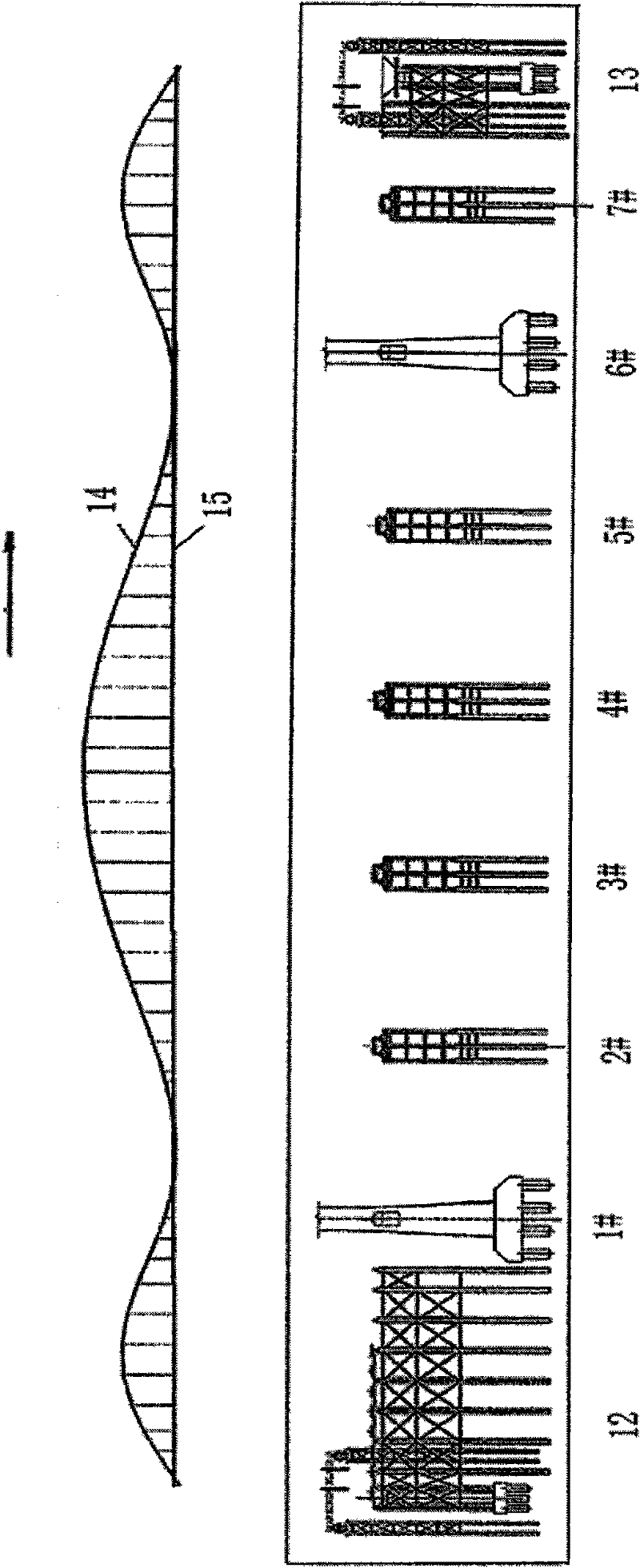
[0015] figure 1 It is a schematic diagram of the pre-camber alignment and temporary pier layout. One end of the bridge is the pushing end 12, and the other end of the bridge is the pushing receiving end 13. There are seven temporary piers in the middle. In order to facilitate the comparison between the pre-camber curve and the corresponding relationship between bridge construction, the pre-camber curve is shown above the bridge piers. 14 among the figure is the pre-camber curve, and 15 is the road design line shape.

[0016] Figure 2a It is a schematic diagram of the jacking when it is pushed to the 3# temporary pier. It can be seen from the figu...


PUM


Abstract

The invention discloses a bridge pushing construction method. In the method, the level of a temporary pier support is adjusted as required to enable a bridge bottom to be in effective close contact with the temporary pier support, thereby actively controlling the counter force of a temporary pier and the internal force of a bridge so as to achieve the same effect with linear or same-radius vertical curve bridge pushing construction. The concrete method is as follows: in the gaps formed by assembling bridge sections, by utilizing a synchronous jack, bulges at convex parts on a curve of the bridge bottom are lifted, and bulges at concave parts are lowered. The pushing construction can be suitable for bridges with change of curvature of vertical curves at bridge bottoms, including bridges with variable heights or bridges provided with multiple sections of composite vertical curves. The bridge pushing construction method disclosed by the invention breaks through and develops the existing bridge construction specification and expands the range of application of pushing construction; and compared with other methods, the bridge pushing construction method can save materials, is fast and safe in construction, and has obvious technical, economic and social benefits.

Description

technical field [0001] The invention relates to the field of bridge construction, in particular to a bridge jacking construction method. Background technique [0002] Pushing construction is a commonly used bridge construction method. A prefabricated assembly platform is set up along the bridge to the background, constructed and assembled in sections, and integrated with the beam body that has been pushed and constructed, and then applied force through a horizontal hydraulic jack. With the help of stainless steel The sliding device composed of PTFE board pushes the top of the beam body out of the prefabricated assembly site, and then continues the prefabricated assembly of the next round of beam sections until the construction is completed. At present, the prefabricated line shape of the bridges installed by the jacking method is mostly a straight line or a circular vertical curve with the same radius; Article 15.5. Curved bridges are only suitable for vertical curved bridg...

Claims


Application Information

Patent Timeline
Patent Type & Authority Applications(China)
IPC IPC(8): E01D21/00
Inventor 郝维索吴东升张剑英沈洋
Owner SHANGHAI MUNICIPAL ENG DESIGN INST GRP
Why Eureka
Eureka Blog
Learn More